Introduction
The core concept of the app is a graph. Graphs represent logic that computes geometry primitives (and other data), which flows through the graph.
A graph is a collection of two main elements:
-
- Individual nodes represent compute functions, like the creation of a polygonal box primitive, a noise generator, or the act of joining two curves.
- This graph has most nodes that exist within the app. Check it out!
- More information can be found in the Node conecept section.
-
- Connections represent the relationship between an output of one node, and the output of another node.
- More information can be found in the Connection concept section.
Together, nodes and connections represent the flow of geometry and data to generate and compute an authored output.
SketchUp Live Components (LCs)
In SketchUp, a Live Component’s behavior is defined by a graph authored in Trimble Creator.
For more info on SketchUp Live Components, see the help page here.
Notable features
There are a couple notable features you'll find in Trimble Creator that were specifically designed or enabled for SketchUp Live Components, they are listed below:
- A Live Component can have a Size frame which can be activated and used by a user in SketchUp using the Scale Tool.
Authoring an LC
In order for a graph to be a Live Component, click on the SketchUp logo button on the left-hand side of the Trimble Creator app. This will take you to a page where you can download an SKP file containing the LC.
Note that the downloaded SKP must be imported in order for the LC to function properly (not just opened directly) as it requires that outer component layer in order to function properly.
Size frame
A size frame defines the positions of grips when the Scale Tool is used on a Live Component in SketchUp.
In Situ
The size frame in SketchUp will automatically appear when using the Scale Tool.
In Graph
Bound Axes
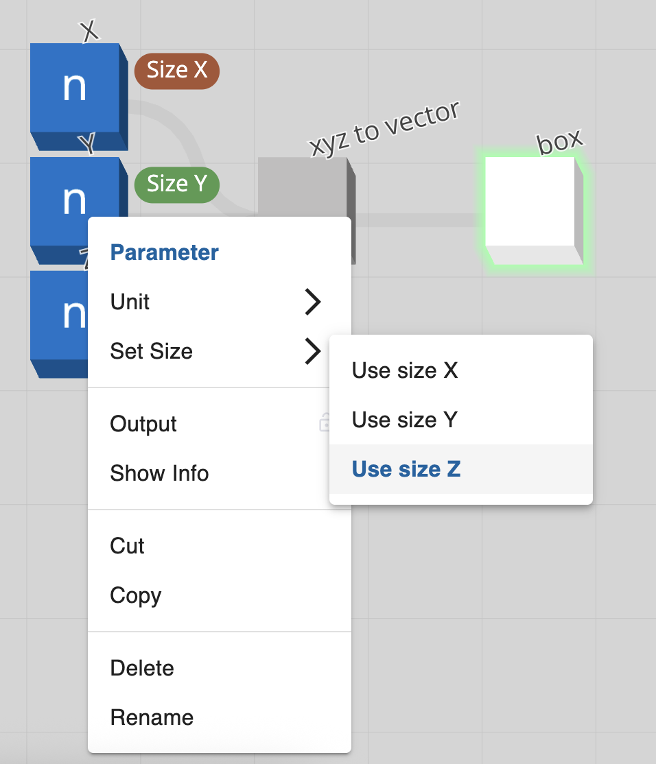
When a size frame’s axis is bound to a parameter and a user stretches the size frame (in SketchUp), the parameter's "value" input will be automatically updated as if the user had directly edited that parameter.
Only either a parameterized number node or parameterized integer node will be able to have a size frame's axis bound to it. To bind a particular axis of a size frame to a particular parameter, right-click a parameterized node and navigate to the "Set Size" menu option. There are three options: Use size X, Use size Y, and Use size Z; each will bind the parameterized node to its respective axis.
Keep in mind that when an axis is bound to a parameter, the parameter receives only the scalar size along that axis, not any directional or orientation information.
Alignment
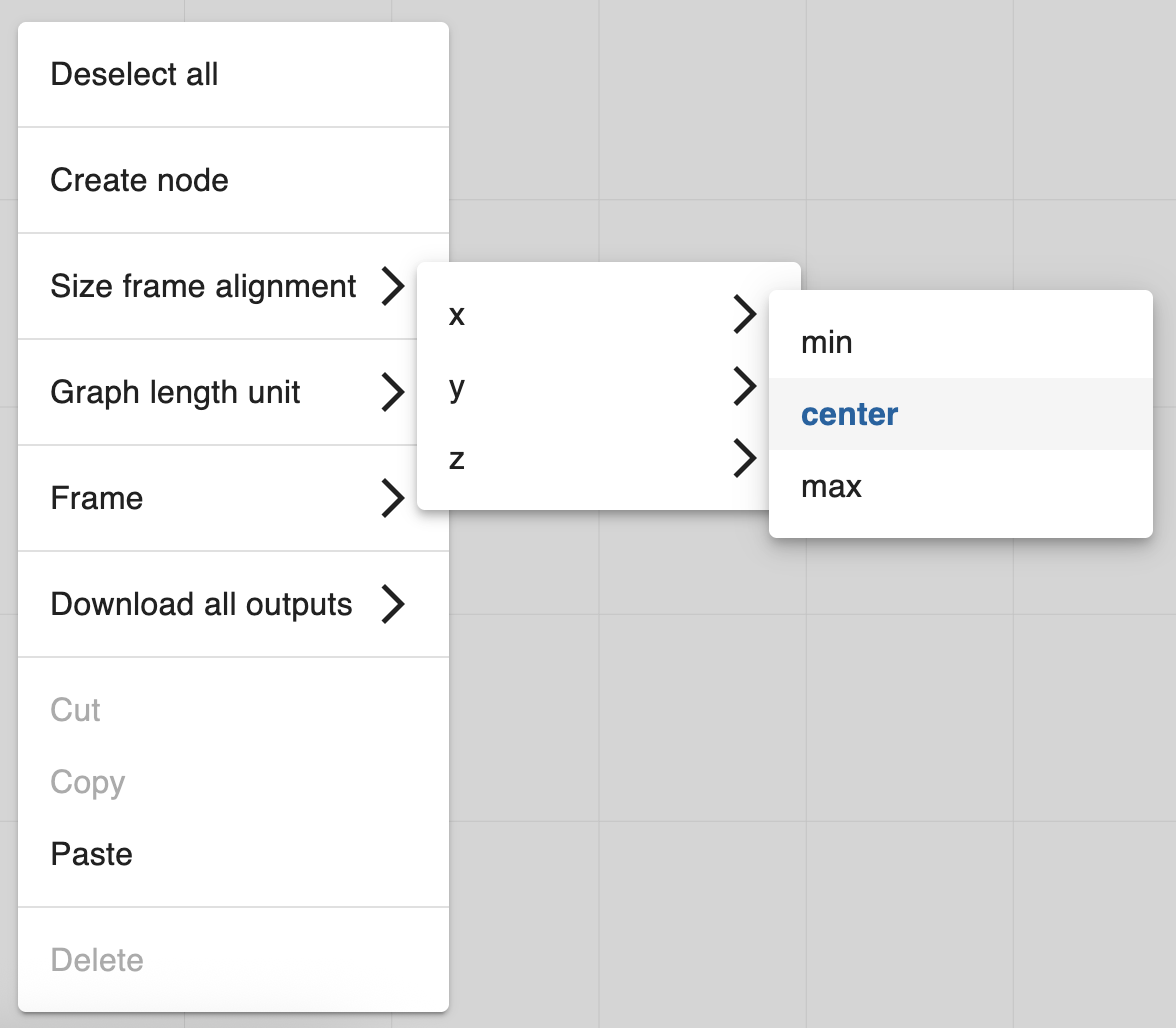
As the size frame is not defined by a Live Component's bounding box (like a normal component), the alignment of the size frame needs to be manually set.
To set the alignment of a size frame, right-click the background of the graph (no nodes or connections) and navigate to the "Size frame alignment" menu option. There are three options: x, y, and z, each with three options: min, center, and max; each will align the size frame by its extents to the world center / 0,0,0.
Notes
- There is only one size frame per Live Component.
- It is important to note that it is up to the author to ensure that the effects of the size frame accurately reflect the expected behavior of the Live Component. Here are a couple of things to look out for:
- Be sure that the size frame's intended alignment matches the geometry it's intended to manipulate
- e.g., the size frame should be aligned to
centerfor each axis if the component is centered on0,0,0.
- e.g., the size frame should be aligned to
- Be sure that the intended direction of a geometry being manipulated by the size frame is behaving as intended.
- e.g., a parameter with a binding of "size x" isn’t changing the size in the y direction.
- Be sure that the size frame's intended alignment matches the geometry it's intended to manipulate
- If you are familiar with the align node, aligning the size frame works similarly to if you were aligning geometry to a
valuerather than other geometry. - Resizing a Live Component with the Scale Tool automatically makes that instance of the Live Component unique.
- The visibility of a Live Component's grips is determined by two things:
- If an axis has been bound to a parameter or not.
- If the bound parameter's "hide control" input is set to
trueor not.
- Visibility of the Scale Tool's edge or corner grips is determined by whether all relevant axes are visible (e.g. if both "size x" and "size y" are bound to parameters and visible, then the edge grips associated with those axes will also be visible).
Examples
- Simple Box (With "correct" parameter bindings)
- Simple Box (With "incorrect" parameter bindings)
- Window Template (Size Frame aligned to min, min, min)
Graph
The core concept of the app is a graph. Graphs represent logic that computes geometry (and other data).
Graphs are a collection of connected nodes.

Graph Concepts
A graph describes:
- A set of particular nodes, and their input and output properties.
- Those nodes' input properity values.
- Connections between those nodes' properties.
- Parameters and their values, which can be considered the graph's input.
- A set of output nodes: which of the above nodes should be computed to obtain the desired result from the graph's logic.
- The ephemeral state of the graph.
The graphs are directed acyclic graphs (DAG) that evaluate lazily.
Node
A node within a graph represents a function.
Each node has a defined set of input and output properties.
Node Input
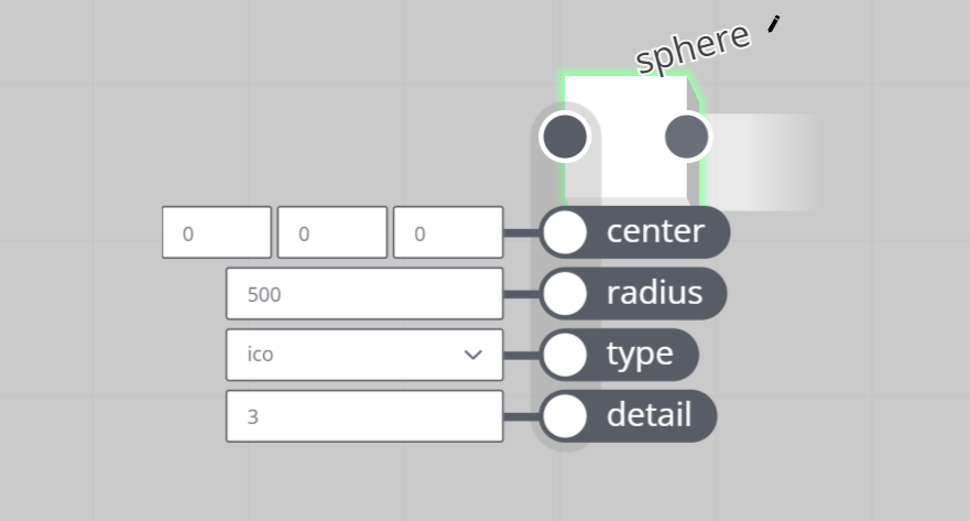
A node has a defined set of inputs, or input properties. Node input properties can be considered the arguments to the function that the node represents. For example: the radius input of a sphere node. Internally this is a float value argument to the function that creates the sphere.
Node inputs can be set directly, but also by other nodes through connections.
For more specifics, see node input and output types.
Node Output
A node also has a defined set of outputs, or output properties. The property values can be considered the result of executing the function that the node represents.

Output values are calculated on compute.
For more specifics, see node input and output types.
Node Error
Nodes can error when the engine has been unable to successfully compute the output of a node. This could be due to a combination of inputs which is impossible to solve, or an internal operator error.
An errored node will cause downstream nodes to error as well, sometimes invalidating the graph's output. Care needs to be taken to avoid putting nodes in an errored state. To un-error an errored node, change its input value(s), which sometimes requires changing upstream node inputs.
An example is dividing by zero using the divide node.

Errors can be 'caught' using graph logic, by the error check node.
Node types
Value & parameter nodes
- These nodes represent base type values, and lists thereof.
- Some value nodes can be tagged as parameters, ie: inputs to the graph.
Geometry creation nodes
- These nodes create geometry primitives.
- Some nodes produce NURBS surfaces/curves, others polygon meshes, etc. Some create multiple types of primitives depending on their input properties.
Geometry modifier nodes
- These are the meat of the graph's compute engine. These nodes take incoming geometry and modify it. Sometimes the input and output geometry are of different primitive types.
Geometry measurement nodes
- These nodes typically convert from geometry input to data: they take geometry primitives as input, but do not feature a geometry output.
Loop & switch nodes
- Loops and switches are special case nodes that enrich the flow in a graph. These nodes allow elegant solutions to complex problems. They reduce graph size, increase performance, and unlock otherwise impossible graph logic.
- A geometry Switch plays a special role in graphs, as it evaluates only one upstream input branch, and blocks evaluation of all other inputs. This contributes to performance.
Math nodes
- The graph features an Experssion node, but simple math problems can be represented by small chains of math nodes. These are orders of magnitude faster than expressions.
- Math nodes can operate on single values, or lists. This includes trigonometry and vector math nodes.
Logic nodes
- Compare values, negate flags, and otherwise combine boolean values.
- Prep (boolean) lists of logical bits to act as filters/masks in the graph.
Mapping, rounding, and clamping nodes
Random number nodes
List nodes
- These nodes manipulate lists of incoming data.
- The graph only features straight lists of a single type. No nested lists or structures.
String nodes
- These nodes manipulate strings.
Rendering nodes
- These nodes provide tools to apply materials and textures to geometry primitives.
- More information on the concept of Materials in the graph can be found in the Material concept section.
Attribute nodes
- Add and extract metadata to/from graphs, nodes, primitives and points.
- More information the concept of Attributes in the app can be found in the Attribute concept section.
Input & Output Types
Geometry
An input or output representing a node's entry and exit point for primitives. This input cannot be set, except by a connection from one or more geometry outputs from other nodes.
Boolean
An input or output representing a binary value: true/false, on/off, show/hide, etc.
- Default value:
false. - Can convert from:
float,integer. - This type is one of the possible value types for parameters, set by a boolean node.
- Examples of valid values:
truefalse
Integer
This is a signed 32bit integer.
- Default value:
0. - Can convert from:
boolean,float. - This type is one of the possible value types for parameters, set by a integer node.
- Examples of valid values:
0-581234567890
Nullable integer
This is a nullable signed 32bit integer.
- Default value:
0. - Can convert from:
boolean,float,null. - The only property which has this type is the value input of an integer node.
- Examples of valid values:
null0-581234567890
Float
This is a 64bit double-precision floating point type.
- Default value:
0.0. - Can convert from:
integer,boolean. - This type is one of the possible value types for parameters, set by a number node.
- Examples of valid values:
00.0-123.4564.567e-8-9.87E+0065
Nullable float
This is anullable 64bit double-precision floating point type.
- Default value:
0.0. - Can convert from:
integer,boolean. - The only property which has this type is the value input of a number node.
- Examples of valid values:
null00.0-123.4564.567e-8-9.87E+0065
Vector
A vector typically represents an XYZ coordinate in 3D space. It is an array of 3 64bit double-precision floating point types.
- Default value:
0, 0, 0 - Can convert from:
color - This type is one of the possible value types for parameters, set by a vector node.
- Examples of valid values:
1, 2, 3-12.34, 56.78, 9.0e-10
Color
A color typically represents an RGB color value. But data-wise, it is essentially the same as a vector type (see above). It is an array of 3 64bit double-precision floating point types.
- The normal value range for each component is 0 to 1, but any double precision value is allowed. For example to obtain high dynamic range coloring.
- Default value:
0, 0, 0 - Can convert from:
vector - This type is one of the possible value types for parameters, set by a color node.
- Examples of valid values:
1, 0, 0(red)0, 2.0, 0(superbright green)0.0, 0, 1(blue)1, 1, 0(yellow)-1.3, 0, 0(negative red; looks cyan; probably not advised!)10.234, 10.567, 5e4(sky blue)
String
- Default value:
""(empty string). - Can convert from:
integer,boolean,float. - This type is one of the possible value types for parameters, set by a string node.
- Examples of valid values:
""(empty string)"1.234""The quick brown fox jumps over the lazy dog.""Chuaigh bé mhórshách le dlúthspád fíorfhinn trí hata mo dhea-phorcáin bhig.""中国俗语"
Enum
The enumeration type is an input type (only) that represents a choice in a list of options, typically displayed as a dropdown menu in a UI .
- Default value:
0. - Can convert from:
integer,boolean,float. - This type is one of the possible value types for parameters, set by a choice node.
Its value is an integer, to denote which option is picked, with 0 meaning the first item in the list provided by the options property of the input.
Connection
A connection is between an output of one node, and an input of another node. Connections define the dependencies of nodes in the graph.
Upstream and downstream nodes describe nodes relative to each other in terms of dependencies. An upstream node's output can be a downstream node's input.
Circular connections/dependencies are impossible in a directed acyclic graphs (DAG). Outputs of a node cannot be connected to the inputs of the same node or upstream nodes.
Connection types
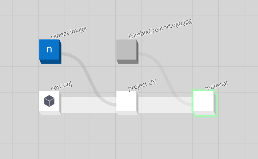
There are two types of connections in the graph. A thicker white connection, which represents the flow of geometry, and a thinner grey connection which represents the flow of data.
Parameter
Parameters can be considered the inputs to a graph. They are created by value type nodes, tagged as parameters. They are often represented by a control in the parameter panel. For example: a slider to control a number parameter, or a color picker for a color parameter.
Consumer type users cannot modify anything other than the value of parameters within a graph.
In the graph depicted below, the "repeat image" node (which is a renamed number node) is a parameter.
Output Node
Any node (or set of nodes) can be tagged as the output of a graph, e.g. by left-clicking the node in the graph viewer. This will enforce compute of these nodes by the compute engine. The computed output of these nodes can be considered the desired output of a graph.
Modification to the graph state will trigger a graph evaluation, and potentially compute.

In the graph depicted above, the green highlighted material node is set to be an output, and as such, computed.
It is possible for multiple nodes to be set to be the graph's output (e.g. by holding the SHIFT key when output selecting nodes in the graph viewer), in which case both of the output selected nodes will be computed.
Import & Export
The graph supports a limited set of geometry and image formats for import and export.
Imported geometry and images files need to be uploaded as assets before they can be used.
Images
Images are primarily used as textures for materials.
The following two formats are supported for upload:
- JPEG / JPG
- PNG
An image that was previously uploaded in one of these formats, can be loaded into a graph using the image asset node.
See the material concept page for more on working with images as textures.
Geometry import
The following formats are supported for import, with noted limitations:
IGES: NURBS curves (126), patches (128), polylines (106) - no trimmed patchesWavefront OBJ: vertices, faces, groups, but no normals, nor UVsDXF: POLYLINE entity type only
Geometry that was previously uploaded in one of these formats, can be loaded into a graph using the geometry asset node.
Geometry export
Geometry can be exported from the graph by either:
- Right mouse button clicking a node, navigating to
Download, and selecting a file format. - Right mouse button clicking the graph background, navigating to
Download all outputs, and selecting a file format.
The latter option will download the geometry from all output selected nodes.
IGES
Exports following primitive types and properties:
Wavefront OBJ
Exports following primitive types:
- Points primitive: points as vertices
- PolyMesh
- NURBS surface, triangulated
Exports:
- Vertices
- Faces: 1 per triangle
- Groups: 1 per primitive
- Normals
- UVs if available
STL
Exports following primitive types:
- PolyMesh
- NURBS surface, triangulated
ASCII STL only. STLs only contain triangle data. No normals, UVs, or groups.
DXF
Exports following primitive types:
- NURBS curve: as DXF Polyline
- Points primitive: as 3D DXF Points
Note that the curves only support 2D coordinates: XY, with Z coordinate effectively zeroed.
TRB
Exports following primitive types:
- PolyMesh, as Faceted BREP
- NURBS surface, triangulated as Faceted BREP
- NURBS curve: as TRB Polyline
- Materials: supports opacity, sideness, base color, base texture, metallicness and roughness.
Exports:
- Vertices
- Faces: 1 per triangle
- Groups: 1 per primitive
- UVs if available
Ephemeral State
Graphs have a boolean value representing their ephemeral state, and this state is exposed to graph logic through the Ephemeral. A graph is in an ephemeral state when parameters are actively being configured/adjusted. For example, when one is dragging a number slider in the parameter panel.
The ephemeral state can, for example, be used to lower detail and compute load when a user is configuring the graph.
For information on ephemeral state and subgraphs, see: Subgraph
Compute
Evaluation
Graph evaluation is used to determine which nodes within the graph require compute. In general, commands changing the graph state will cause the graph to be evaluated.
Evaluation determines the 'upstream' dependencies of a graph's output nodes.
The graph utilises lazy evaluation to determine the need for compute. Not all nodes in the graph will necessarily be computed every cycle. In general, nodes 'downstream' of changed nodes, and 'upstream' of a graph's output nodes, are candidates for compute.
Compute
Compute is the act of executing the logic described by a graph. Compute will occur after graph evaluation, if required.
Below is a visualisation of a simple graph containing three nodes and the 3d view representing the computed output of graph:
In this visualisation the highlighted node is set to be an output node of this graph, and as such, computed.
- The box node named "box" creates a polygonal box primitive on compute.
- The sphere node named "sphere" creates a polygonal sphere primitive on compute.
- The collect node named "collect" does not modify or create geometry. It simply collects input primitives and outputs these on compute.
- "box" node is set to be an output node.
- Graph state is updated and evaluated.
- "box" node computes and displays in the 3d view.
- "sphere" node is set to be an output node.
- Graph state is updated and evaluated.
- "sphere" node computes and displays in the 3d view.
- "collect" node is first set to be an output node.
- Graph state is updated and evaluated.
- "collect" node computes and outputs nothing (as the "collect" node creates creates nothing itself).
- "box" node's output is connected to the input of the "collect" node.
- Graph state is updated and evaluated.
- "collect" node computes and displays the box.
- "sphere" node's output is additionally connected to the input of the "collect" node:
- Graph state is updated and evaluated.
- "collect" node computes and the view displays both the sphere and the box.
It is possible for multiple nodes to be set to be the graph's output. In this example, if the "box" node and "sphere" node were both set to be output nodes, the compute result would be a polygonal box and sphere.
Subgraphs
A subgraph is a fully functional graph loaded within another graph. This is done by loading of a previously saved graph asset, using a graph asset node.
The graph is thus represented as a node, with
- The graph's parameters as the node's input,
- The graph's computed primitives (all primitives of all output nodes) as the node's output.
This makes graphs a nestable, or recursive, concept.
Care needs to be taken not to cause an infinite nesting loop, where graph A is nested in graph B, nested in graph A.
The parameters of a nested graph need to be provided to the graph asset node's parameters input as a JSON string containing key-value pairs of the nested graph's parameters. For example:
{"Parameter A":3.14, "Parameter B":666,"Parameter C":42}
The graph asset node's URI input takes a graph assetURI, which triggers load (and compute) of this referenced graph on compute of the parent graph's graph asset node. Example of an asset URI:
whp:d65f2b43-7c90-4f45-97d0-d03b93abff85
Ephemeral behavior
A nested graph inherits its ephemeral state from its parent graph. Specifically, a graph asset node will retrieve its parent graph's ephemeral state and forwards the state to its internal graph object only at the node's compute time, before the internal graph is evaluated.
Primitive
Primitives are a graph's's computed entities. They are created and transformed by nodes, and flow through the nodes and connections of a graph.
Examples of primitives:
PolyMesh: a 3D polygonal mesh primitive.NURBS curveandNURBS surface: a NURBS curve and NURBS surface primitive.
Consider this graph:

The circle node creates a NURBS curve primitive, and the sphere node creates a PolyMesh primitive.

Both primitives get passed downstream to the collect node. In its turn, the collect node passes the two collected primitives on downstream to any node connected to its output.

In this case, the primitives pass through the collect node unchanged, but other node types have the ability to transform and modify incoming primitives. Example: an extrude mesh node will extrude the polygons of any incoming PolyMesh primitive, but not NURBS curve primitives.
PolyMesh
A PolyMesh is a primitive representing a 3D polygonal mesh. A PolyMesh has following notable properties:
- vertices: A list of 3D vectors representing the 3D coordinates of the mesh's vertices.
- indices: A list of integer indices into the list of vertices. Three consecutive indices define a single triangle. Triangles can share vertices. Example: indices of a PolyMesh with 2 triangles sharing 2 vertices:
[0, 1, 2, 1, 2, 3]. - normals (optional): A list of normalised 3D vectors representing the vertex normals of the mesh. One normal per vertex, exactly.
- UVs (optional): A list of 2D vectors representing the UV texture coordinates of the mesh. One vector per vertex, exactly.
NURBS curve
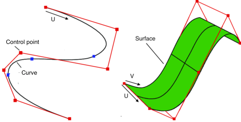
A NURBS curve is a primitive representing a 3D NURBS curve. These curves are smooth mathematical spline interpolations of a set of control points. A NURBS curve is parametrised along a U coordinate, varying between 0 and 1.
A NURBS curve has following notable properties:
- control points: a list of 3D vectors representing the 3D coordinates of the points that define the curves's mathematical spline function.
- order: a positive integer defining the number of nearby control points that influence any given point on the curve. Practically: the higher the number, the smoother the curve. Order 2 effectively turns the curve into a polyline connecting the control points with straight line segments.
For more indepth information on how weights of NURBS curves work, visit here: modifying NURBS curve weights. This can be done in the graph with the use of the set point weight node.
NURBS surface
A NURBS surface is a primitive representing a 3D NURBS surface. A NURBS surface always has a rectangular topology, with coordinates in two axes: U and V values varying between 0 and 1.
NURBS curves and surfaces lend themselves well to parametric modeling applications. For example, one can easily extract a NURBS curve from a NURBS surface's particular U or V value, or create a NURBS surface from several NURBS curves.
A NURBS surface has following notable properties:
- control points: a list of 3D vectors representing the 3D coordinates of the points that define the surfaces's mathematical spline function.
- order (in both U and V direction): a positive integer defining the number of nearby control points that influence any given point on the surface in U or V direction. Practically: the higher the number, the smoother the surface. Order 2 effectively makes the surface faceted.
Points
A Points primitive is a bare-bones primitive representing a set of 3D points. It is, for example, created by the points node.
Locator
A locator is a point with orientation.
Some typical use cases of a locator:
- An indicator of an important location in a 3D scene or object.
- A placeholder for a more complex 3D object.
- As a snap or connection point between 3D objects.
- A grip or handle to move geometry in a 3D view.
- A lightweight carrier of metadata or attributes.
Locator primitive
The locator concept is expressed via a LocatorPrimitive. This primitive is essentially a point with orientation. It has the following properties:
- An ID: a user-settable persistent ID
- A transform matrix: this gives the locator its position and orientation.
- Semantic type: can be used to turn a locator into a more complex concept, like a snapping point.
- This primitive is a 3D object, and can be transformed like one, for example using a transform node.
As with all primitives, it can carry attributes.
Locator node
To create one or more locators, use the locator node.
Attribute
Attributes are metadata that can be attached to primitives, points, nodes, and graphs.
Attributes "piggy back" on points and primitives as they flow through the graph. This avoids the need to use separate graph branches for metadata and geometry.
If so desired, attributes can also enrich the computed output with custom data that is industry or application-specific.
Examples:
- Attach IFC (Industry Foundation Classes) data to the geometry of architectural products, like doors and windows.
- Enrich locators to become connectors or snapping points.
Attribute value types
Attributes can be of the following value type:
- Number (example:
1.234) - String (example:
"ABC") - Vector (example:
[1, 2, 3])
Attribute name
Each attribute has a given name.
Types of attributes
Attributes are computed state, carried by nodes.
Attributes are node centric. So for example, primitive attributes cannot be different per-primitive in a node. Nor can point attributes. Every primitive in a node is paired to the same point and primitive attributes.
Point
Point attributes come in list form. This is list of attribute values, paired to primitives' points.
Each point attribute's list contains one list item per point in the computed output of a node. The list is as long as the total number of points across all primitives in a node's computed output.
So if a computed node contains two primitives, one with 10 points and another with 20 points, the point attribute lists will be 30 items long.
Primitive
Primitive attributes come in list form. This is list of attribute values, paired to primitives of a node.
Each primitive attribute's list contains one list item per primitive in the computed output of a node. The list is as long as the total number of primitives in a node's computed output.
So if a computed node contains 10 primitives, the primitive attribute lists will be 10 items long.
Node
Node attributes are single values, and get passed downstream from node to node in the directed acyclic graph (DAG) flow of a graph.
Graph
Node attributes are single values, and get set at the graph level.
Best to declare graph attributes only once.
Attribute merging
When attributes flow through a graph's DAG, some some merging rules apply.
Point and primitive attributes
As noted above, attributes are node centric. All primitives and points in a node's computed output must carry the exact same attributes.
The graph will fill in the gaps. If a set of primitives with attributes A and B get merged with primitives carrying attribute C, the graph will extend attribute A and B to the second batch of primitives, and C to the first batch, so that the current node's primitives all carry A, B and C.
Default values for each type are used to fill the gaps:
- Number :
0 - String:
"" - Vector:
0,0,0
Node attributes
If two or more incoming nodes carry the same node attribute, the last connected input node will be the one used.
Graph attributes
If the same graph attribute is declared on two or more nodes, the last evaluated node will be the one used. Note that this can lead to unexpected results. It is likely better to make sure a graph attribute is only declared once.
Nodes
All types of attributes can be added using the add attribute node.
The get attribute node allows querying of attribute metadata to/from graphs, nodes, primitives and points.
Assets
Assets are representations of stored data. E.g. a graph created by a user. Other types of assets may be external in origin and uploaded, e.g. an IGES or OBJ model.
Asset types
Any file can be an asset, but in practice only the following asset types are relevant:
- The primary asset is a graph.
- A few geometry formats are recognized. Geometry files need to be stored as assets to be used.
- A few image formats are recognized for use as material textures. They too need to be stored as assets to be used.
See the Import & Export page for a list of supported formats.
Asset policies
Key asset policies:
- Assets can be saved, but not deleted.
- All assets are versioned in version streams.
- An asset can be owned by a single user, determined by the first version of the asset, or it can be owned by an organization if the user saved the asset while acting on behalf of that organization.
- The user must own the asset to save a new version of it.
- There are limits to asset uploading. See section below.
Storing assets
Save
There are multiple states in which a graph can be saved. Saving will:
- Start a new asset version stream if the current asset has not been saved previously under the current user or organization.
- Version up an existing version stream.
- If the asset name has changed, saving will either:
- Start a new asset version stream.
- Version up an existing version stream.
- If the asset name has changed to an existing asset with that name, saving will prompt to either:
- Version up an existing version stream.
- Rename the graph and
Asset URI
All assets are associated with a unique database identifier. It is a unique hash with a prefix specifying the asset storage provider.
For example, assets stored in the Trimble Warehouse Platform database use the whp: prefix, as in:
whp:e6266721-3266-4065-bd90-d263fa568966
Upload limits
These are the approximate limits for asset uploading:
- 20MB per asset
- 100MB per session
- 100 uploads per session
Material
Every primitive flowing through a graph has a material property.
Here's an example:

Materials are particularly relevant for surface type primitives like PolyMesh and NURBS surface. But they are used for other purposes as well. The color channel of the material gives a NURBS curve its color, for example.
The material node modifies a primitive's material settings.
This is the graph that generated the rendering above:
PBR Shading
Trimble Creator materials implement a metallic-roughness shading model. This type of shading is used in Physically Based Rendering (PBR) renderers.
For more on rendering, metallic-roughness shading and PBR, see the PBR shading guide from Adobe Substance.
Albedo
Albedo is the 'diffuse' or 'base' color of the primitive it is assigned to.
Albedo color can be varied across a surface using a texture.
The range of red, green and blue color values is 0 to 1 for the texture. These values can be multiplied with the provided color value. Resulting values above 1 are supported in PBR shading, and just indicate superbright colors.
Default is white.
Opacity
Opacity is the inverse of the transparency of the primitive it is assigned to.
- An opacity of 0 means the object is totally transparent.
- An opacity of 1 means the object is not transparent at all. This is the default.
Opacity can be varied across a surface using a texture. The texture overrides the provided opacity value.
Roughness
Roughness is an indication of how rough, smooth or 'diffuse' the primitive's surface is. It simulates microscopic imperfections (or lack thereof) of the surface.
Chalk is very rough. A glass window is not.
Roughness can be varied across a surface using a texture. Using a grayscale image is recommended.
Roughness value range is 0 to 1. Texture values can be multiplied using a provided multiplier value.
Default is 1 (fully rough, or diffuse).
Metallic
The metallic property is an indication of how much a primitive's surface acts like a metal.
Metallic can be varied across a surface using a texture. Using a grayscale image is recommended.
Metallic value range is 0 to 1. Texture values can be multiplied using a provided multiplier value.
Default is 0 (not metallic).
Reflectance
Reflectance is an indication of how reflective or 'specular' the primitive's surface is.
Reflectance can be varied across a surface using a texture. Using a grayscale image is recommended.
Reflectance value range is 0 to 1. Texture values can be multiplied using a provided multiplier value.
Default is 0 (not reflective, nor specular).
Bump
A bump map is used to simulate geometric detail on a surface it is applied to.
Bump requires a texture, and UV coordinates. The graph assumes the red channel of the texture will be used to perturb the normal as a derivative map. A derivative map uses a greyscale texture (or if a color image, the red channel thereof) to generate a normal map on-the-fly.
Bump value range is 0 to 1 for the texture, but can be multiplied using a provided multiplier value. Negative values will invert the bump details.
Default is 0 (no bump).
Incandescence
Incandescence or emissivity of an object is a color indicating how much a surface acts as a light. Even if nothing is lighting the scene, an emissive object will be visible.
Some renderers can use this property to make the object cast light into the scene.
Incandescence color can be varied across a surface using a texture.
The range of red, green and blue color values is 0 to 1 for the texture. These values can be multiplied with the provided color value. Resulting values above 1 are supported in PBR shading, and just indicate superbright emission color.
Default is black (no emission).
Double-sided
If switched off, the double-sided property is used to indicate to renderers that only one side of a primitive's surface should be rendered. The side the surface the normal is pointing out from.
Default is both sides. Note that many renderers assume single-sided is the default, causing a surface to become invisible from some viewing angles.
Texture size
This sizing factor is a multiplier on the primitive's UV coordinates. UV coordinates are required on the geometry primitives if textures are used for any of the above properties.
Default is 1 (no scaling).
Nodes
The material node modifies a primitive's material settings. The node can modify specific shading properties, and leave the other properties as-is. Multiple material nodes can be used in sequence to affect different shading aspects of primitives.
The set color node modifies a primitive's albedo color.
Textures
Textures are images used to 'map' certain shading properties, like base color, roughness, or bump. This allows for variation of the property across the surface of geometry primitives. Example: make only parts transparent, or reflective.
Import textures by uploading them. They can then be loaded into a graph using the image asset node.
To use them with materials, connect their asset uri output to the desired texture input of a material node.
UV mapping
Whenever a texture is used in a material to vary a shading property across a surface geometry primitive, that primitive needs to carry UV coordinates. This is so there is a map between pixels of the texture and 3D locations on the geometry's surface.
NURBS surface primitives carry UVs by design, but PolyMesh primitives sometimes need UVs to be added.
In general, this requires sophisticated UV mapping tools. This node provides basic ways of to applying UV coordinates onto PolyMesh primitives: project UV.
Boolean
Creates a boolean value.
Inputs
-
value
- Boolean value to output.
-
default
- The default value to output when the set to default input is set to
true.
- The default value to output when the set to default input is set to
-
set to default
- Sets the value input to the value defined by the default input.
-
hide control
- Hides the parameter control within the parameter panel when the node is parameterized.
-
hide label
- Hides the parameter label (name) within the parameter panel when the node is parameterized.
Outputs
-
value
- The boolean value as defined by the value input.
Notes
-
When parameterized this node will appear as a false/true toggle in the parameter panel.
-
A boolean value is in essence a
0or1integer value.0isfalseand1istrue. -
The value input can accept any numerical value (floating value or integer). The boolean node will convert a value of
0tofalse(0) whereas any other value other than0will returntrue(1). -
Other names for this node include: BooleanValue, Checkbox, State, Bit, Binary, On/Off, True/False, or Parameter.
Examples
Choice
Creates an enumeration (choice), shown as a dropdown.
Inputs
-
value
- The option index and text to output.
-
options
- A comma separated list of options (e.g.
Option1,Option2,Option3).
- A comma separated list of options (e.g.
-
index offset
- Offset the chosen option index by this value.
-
default index
- The default option index to output when the set to default input is set to
trueor the value input is reset.
- The default option index to output when the set to default input is set to
-
set to default
- Sets the value input to the option index defined by the default index input.
-
reset mode
- Sets the mode in which the option index is reset to the value defined by the default index input. This can be
when any input changes(resets the value input whenever a connected input is changed) ordo not reset index(does not reset the value input at all).
- Sets the mode in which the option index is reset to the value defined by the default index input. This can be
-
hide control
- Hides the parameter control within the parameter panel when the node is parameterized.
-
hide label
- Hides the parameter label (name) within the parameter panel when the node is parameterized.
Outputs
-
value
- The chosen option index as defined by the value input (with offset as defined by the index offset input).
-
text
- The chosen option text as defined by the value input.
Note(s)
-
When parameterized this node will appear as a dropdown in the parameter panel.
-
Other names for this node include: EnumValue, Dropdown, Menu, Choose, Enum, Enumeration, Parameter.
Examples
Color
Creates a color (vector) value.
Inputs
-
value
- The color value to output.
-
default
- The default value to output when the set to default input is set to
true.
- The default value to output when the set to default input is set to
-
set to default
- Sets the value input to the value defined by the default input.
-
hide control
- Hides the parameter control within the parameter panel when the node is parameterized.
-
hide label
- Hides the parameter label (name) within the parameter panel when the node is parameterized.
Outputs
-
value
- The color value as defined by the value input.
Note(s)
-
When parameterized this node will appear as three input fields and a color picker in the parameter panel.
-
A color value is defined by three values between
0and1.-
Any input value above
1will be rounded back down to1. -
Any input value below
0will be rounded back up to0. -
The
0-1range is the same as the RGB0-255range. See the range node to convert individual values.
-
-
Any vector values can be utilized as a color value.
-
A color value can be set via the “color picker” by clicking on the colored box next to the value and default inputs.
-
Other names for this node include: ColorValue and Parameter.
Examples
Integer
Creates an integer (whole number) value.
Inputs
-
value
- The integer value to output.
-
default
- The default value to output when the set to default input is set to
trueor the value input isnull.
- The default value to output when the set to default input is set to
-
set to default
- Sets the value input to the value defined by the default input.
-
min/max mode
- The mode in which the value input is constrained. See the Note(s) section below for more information.
-
min
- The minimum value of the slider range.
-
max
- The maximum value of the slider range.
-
hide control
- Hides the parameter control within the parameter panel when the node is parameterized.
-
hide label
- Hides the parameter label (name) within the parameter panel when the node is parameterized.
-
hide input field
- Hides the parameter input field within the parameter panel when the node is parameterized.
-
hide slider
- Hides the parameter slider within the parameter panel when the node is parameterized.
Outputs
value
- The integer value as defined by the value input.
input is null
- Outputs a boolean value that indicates whether the value input is
null(true) or not (false).
Notes
-
When parameterized this node will appear as a slider and input field in the parameter panel.
-
Setting a min/max mode input to
Softwill allow values outside the range of the values defined by the relevant min and max inputs. Setting it toHardwill not allow values outside the range of the values defined by the relevant min and max inputs (thus clamping any values to this range). -
Other names for this node include: IntegerValue, Whole, Number, and Parameter.
Examples
Number
Creates a number (floating point) value.
Inputs
-
value
- The number value to output.
-
default
- The default value to output when the set to default input is set to
trueor the value input isnull.
- The default value to output when the set to default input is set to
-
set to default
- Sets the value input to the value defined by the default input.
-
min/max mode
- The mode in which the value input is constrained.
-
min
- The minimum value of the slider range.
-
max
- The maximum value of the slider range.
-
hide control
- Hides the parameter control within the parameter panel when the node is parameterized.
-
hide label
- Hides the parameter label (name) within the parameter panel when the node is parameterized.
-
hide input field
- Hides the parameter input field within the parameter panel when the node is parameterized.
-
hide slider
- Hides the parameter slider within the parameter panel when the node is parameterized.
Outputs
-
value
- The integer value as defined by the value input.
-
input is null
- Outputs a boolean value that indicates whether the value input is
null(true) or not (false).
- Outputs a boolean value that indicates whether the value input is
Notes
-
When parameterized this node will appear as a slider and input field in the parameter panel.
-
Setting a min/max mode input to
Softwill allow values outside the range of the values defined by the relevant min and max inputs. Setting it toHardwill not allow values outside the range of the values defined by the relevant min and max inputs (thus clamping any values to this range). -
Other names for this node include: FloatValue, Float, Double, Decimal, Real, and Parameter.
Examples
String
Creates a string value.
Inputs
-
value
- The string value to output.
-
default
- The default value to output when the set to default input is set to
true.
- The default value to output when the set to default input is set to
-
set to default
- Sets the value input to the value defined by the default input.
-
hide control
- Hides the parameter control within the parameter panel when the node is parameterized.
-
hide label
- Hides the parameter label (name) within the parameter panel when the node is parameterized.
Outputs
-
value
- The string value as defined by the value input.
Notes
-
When parameterized this node will appear as an input field in the parameter panel.
-
Other names for this node include: StringValue, Text, Word, and Parameter.
Examples
Vector
Creates an xyz vector value.
Inputs
-
value
- The vector value to output.
-
default
- The default value to output when the set to default input is set to
true.
- The default value to output when the set to default input is set to
-
set to default
- Sets the value input to the value defined by the default input.
-
hide control
- Hides the parameter control within the parameter panel when the node is parameterized.
-
hide label
- Hides the parameter label (name) within the parameter panel when the node is parameterized.
Outputs
-
value
- The vector value as defined by the value input.
Notes
-
When parameterized this node will appear as three input fields in the parameter panel.
-
The order of the individual input boxes for the value and default inputs are (from left to right): x, y, and z.
-
Other names for this node include: VectorValue, Point, Coordinate, Direction, xyz, and Parameter.
Examples
Boolean list
Creates a list of boolean values.
Inputs
-
list
- The boolean list to output.
-
size
- The size (length) of the list to output when the initialize input is set to
true.
- The size (length) of the list to output when the initialize input is set to
-
default
- The default value to output when the initialize input is set to
true.
- The default value to output when the initialize input is set to
-
pattern
- Sets the list input to a pattern of boolean values as defined by the start, end, skip, and every inputs when the initialize input is set to
true.
- Sets the list input to a pattern of boolean values as defined by the start, end, skip, and every inputs when the initialize input is set to
-
start
- The index of the list input where the pattern starts.
-
end
- The index of the list input where the pattern ends.
-
skip
- The number of indexes to skip within a repeated section of the pattern of the list input.
-
every
- The number of indexes within a repeated section of the pattern of the list input.
-
initialize
- Sets the list input values as per the values of the size, default, pattern, start, end, skip, and every inputs.
Outputs
-
list
- The boolean list as defined by the list input.
Notes
-
A custom list can be made by clicking on the
<boolean list>space of the list input via the “Add Item” button. -
When the initialize input is set to
true, any values manually entered into the list input will be replaced with the default input value. -
When the initialize input is
true, manually inputted values will be overridden by the default input value. -
The pattern input:
- When both the initialize and pattern inputs are set to
true, the default input (and therefore list input) will be replaced with the pattern set by the start, end, skip, and every inputs. - Changing the default input value will invert the set pattern.
- List indexes outside of the pattern range (as set by the start and end inputs) will be set to the value according to the default input.
- When both the initialize and pattern inputs are set to
-
Other names for this node include: BooleanList, Mask, and Bitmask.
Examples
Integer list
Creates a list of integer values.
Inputs
-
list
- The integer list to output.
-
size
- The size (length) of the list to output when the initialize input is set to
true.
- The size (length) of the list to output when the initialize input is set to
-
iterator
- Sets the list input to an iterative (sequential) list of integer values (i.e. 0, 1, 2, …, n) when the initialize input is set to
true.
- Sets the list input to an iterative (sequential) list of integer values (i.e. 0, 1, 2, …, n) when the initialize input is set to
-
default
- The default value to output when the initialize input is set to
true.
- The default value to output when the initialize input is set to
-
initialize
- Sets the list input values as per the values of the size, iterator, and default inputs.
Outputs
-
list
- The integer list as defined by the list input.
Notes
-
A custom list can be made by clicking on the
<integer list>space of the _list _input via the “Add Item” button. -
When the initialize input is
true, manually inputted values will be overridden by the default input value. -
When both the initialize and iterator inputs are
true, the iterative values override the default input value. -
Other names for this node include: IntegerList, Number list.
Examples
Number list
Creates a list of number (floating point) values.
Inputs
-
list
- The number list to output.
-
size
- The size (length) of the list to output when the initialize input is set to
true.
- The size (length) of the list to output when the initialize input is set to
-
default
- The default value of the list to output when the initialize input is set to
true.
- The default value of the list to output when the initialize input is set to
-
initialize
- Sets the list input values as per the values of the size and default inputs.
Outputs
-
list
- The number list as defined by the list input.
Notes
-
A custom list can be made by clicking on the
<number list>space of the list input via the “Add Item” button. -
When the initialize input is
true, manually inputted values will be overridden by the default input value. -
Other names for this node include: FloatList, Float list and Decimal list.
Examples
String list
Creates a list of string values.
Inputs
-
list
- The string list to output.
-
size
- The size (length) of the list to output when the initialize input is set to
true.
- The size (length) of the list to output when the initialize input is set to
-
default
- The default value of the list to output when the initialize input is set to
true.
- The default value of the list to output when the initialize input is set to
-
initialize
- Sets the list input values as per the values of the size and default inputs.
Outputs
-
list
- The string list as defined by the list input.
Notes
-
A custom list can be made by clicking on the
<string list>space of the list input via the “Add Item” button. -
When the initialize input is
true, manually inputted values will be overridden by the default input value. -
Other names for this node include: StringList, Text list, and Word list.
Examples
Vector list
Creates a list of xyz vector values.
Inputs
-
list
- The vector list to output.
-
size
- The size (length) of the list to output when the initialize input is set to
true.
- The size (length) of the list to output when the initialize input is set to
-
default
- The default value of the list to output when the initialize input is set to
true.
- The default value of the list to output when the initialize input is set to
-
initialize
- Sets the list input values as per the values of the size and default inputs.
Outputs
-
list
- The vector list as defined by the list input.
Notes
-
A custom list can be made by clicking on the
<vector list>space of the list input via the “Add Item” button. -
When the initialize input is
true, manually inputted values will be overridden by the default input value. -
Other names for this node include: VectorList, Point list, Coordinate list, Direction list, and xyz list.
Examples
Boolean 2d paths
Performs 2D boolean operations on curves/polygons.
Inputs
-
geometry
- Accepts multiple geometry connections.
-
work plane
- The work plane in which the 2D boolean operation will be performed in. This can be
X=0,Y=0, orZ=0.
- The work plane in which the 2D boolean operation will be performed in. This can be
-
pre-flatten
- Flattens the input curves/polygons into the work plane defined by the work plane input before the 2D boolean operation.
-
boolean type
- Sets the type of 2D boolean operation to be performed. This can be
intersect,union,difference, orxor.
- Sets the type of 2D boolean operation to be performed. This can be
-
fill type
- Sets the type of fill that is considered when the 2D boolean operation is performed. For more information visit: http://www.angusj.com/delphi/clipper/documentation/Docs/Units/ClipperLib/Types/PolyFillType.htm
-
primary polygon
- Sets which input curve/polygon is to be considered as the primary polygon in the 2D boolean operation. This can be the
firstorlastof the list of input curves/polygons.
- Sets which input curve/polygon is to be considered as the primary polygon in the 2D boolean operation. This can be the
-
primary role
- Sets the role of the primary curve/polygon (as defined by the primary polygon input). This can be
clip(the curve/polygon to operate with), orsubject(the curve/polygon to operate on).
- Sets the role of the primary curve/polygon (as defined by the primary polygon input). This can be
-
close resulting curves
- Sets whether to close the resulting curves/polygons after the 2D boolean operation.
Outputs
-
geometry
- Output primitives.
-
points
- The list of points of the output curve/polygon primitives.
-
points.x
- The list of x values of the points of the output curve/polygon primitives.
-
points.y
- The list of y values of the points of the output curve/polygon primitives.
-
points.z
- The list of z values of the points of the output curve/polygon primitives.
Note(s)
-
2D boolean operations are projected back to the selected work plane defined by the work plane input.
- If pre-flatten is
false, then all curves that are to be operated on need to be on the defined work plane. Otherwise the operation will fail, or curves/polygons will be excluded from the operation.
- If pre-flatten is
-
Requires at least two curve/polygon input primitives.
-
Other names for this node include: CurveBoolean, Curve boolean, and Polygon boolean.
Examples
Offset 2d path
Offsets curves in the chosen workplane.
Inputs
-
geometry
- Accepts a single geometry connection (unless the SHIFT key is held).
-
work plane
- The work plane in which the 2D offset operation will be performed in. This can be
X=0,Y=0, orZ=0.
- The work plane in which the 2D offset operation will be performed in. This can be
-
pre-flatten
- Flattens the input curves into the work plane defined by the work plane input before the 2D offset operation.
-
offset
- The distance the input curves will be offset.
-
join
- Sets the type of join that will be performed at the vertices of the 2D offset. This can be
miter,square,round, orsimple (none).
- Sets the type of join that will be performed at the vertices of the 2D offset. This can be
-
miter limit
- The distance limit before a miter join is made. If joins of an offset are beyond the limit, then a bevel join will be made at the limit value.
-
arc precision
- The level of precision of the round join offset. The closer to
0, the higher the precision of the rounded join.
- The level of precision of the round join offset. The closer to
-
close resulting curves
- Sets whether to close the resulting curves after the 2D offset operation.
Outputs
-
geometry
- Output primitives.
-
points
- The list of points of the output curve primitives.
-
points.x
- The list of x values of the points of the output curve primitives.
-
points.y
- The list of y values of the points of the output curve primitives.
-
points.z
- The list of z values of the points of the output curve primitives.
Notes
-
Both the miter limit and arc precision inputs only affect the
miterandroundjoin types respectively and will only be available when those types are defined in the join input. -
Other names for this node include: OffsetCurve, Offset curve, and Offset polygon.
Examples
Add attribute
Adds attributes (metadata) to points, primitives, nodes, or graphs.
Inputs
-
geometry
- Accepts a single geometry connection (unless the SHIFT key is held).
-
type
- Sets the type of attribute to add. These are
per point(added to each point of the input primitives),per primitive(added to each of the input primitives),on node(added to the node), andon graph(added to the graph).
- Sets the type of attribute to add. These are
-
attribute name
- The name to give the attribute.
-
value
- The value to assign to the attribute. This can be any of the basic data types (number (number, integer, and boolean), vector (vector and color), or string).
Outputs
-
geometry
- Output primitives.
-
points
- The list of points of the output primitives.
-
points.x
- The list of x values of the points of the output primitives.
-
points.y
- The list of y values of the points of the output primitives.
-
points.z
- The list of z values of the points of the output primitives.
Note(s)
-
See Attribute for more information on attributes, and their function in the graph.
-
This node can be used in conjunction with the get attribute node to later retrieve the attribute data.
-
Other names for this node include: AddAttribute, Set attribute and Write attribute.
Examples
Get attribute
Extracts attribute (metadata) by name and data type.
Inputs
-
geometry
- Accepts a single geometry connection (unless the SHIFT key is held).
-
type
- Sets the type of attribute to add. This can be
per point(added to each point of the input geometry),per primitive(added to each primitive of the input geometry),on node(added to the node), oron graph(added to the graph).
- Sets the type of attribute to add. This can be
-
attribute name
- The name to give the attribute.
-
value
- The value to assign to the attribute. This can be any of the basic data types (number (number, integer, and boolean), vector (vector and color), and string).
Outputs
-
points
- The list of points of the output primitives.
-
points.x
- The list of x values of the points of the output primitives.
-
points.y
- The list of y values of the points of the output primitives.
-
points.z
- The list of z values of the points of the output primitives.
Notes
-
See Attribute for more information on attributes, and their function in the graph.
-
The value input is a special type of input that can accept any type of data.
-
Other names for this node include: GetAttribute, Attribute to list, and Read attribute.
Examples
Copy
Copies and transforms geometry.
Inputs
-
geometry
- Accepts multiple geometry connections.
-
# of copies
- The number of copies to make of the input primitives.
-
translate
-
The vector value that defines how much each copy will be translated (moved). Each copy of the input primitives will be translated from the transform of the previous copy.
-
For example, a box with a center at
0,0,0is copied at a translate input of500,0,0. The first copy will be translated to500,0,0, the second copy will be translated another500,0,0for a total translation of1000,0,0, and so on.
-
-
rotate
-
The vector value that defines how much each copy will be rotated. Each copy of the input primitives will be rotated from the transform of the previous copy.
-
For example, a box with a starting rotation of
0,0,0is copied at a _rotate _input of0,0,45. The first copy will be rotated by0,0,45, the second copy will be rotated another45,0,0for a total rotation of0,0,90(from the original input primitives), and so on.
-
-
scale
-
The vector value that defines how much each copy will be scaled. Each copy of the input primitives will be scaled from the transform of the previous copy.
-
For example, a box (with dimensions
1000,1000,1000) is copied at a scale input of1,1,1.5. The first copy will be scaled by1.5,1.5,1.5(now with dimensions of1000,1000,1500), the second copy will scale the first copy (that has the dimensions of1000,1000,1500) by1,1,1.5(now with dimensions of1000,1000,2250), and so on.
-
-
uniform scale
-
The value that defines how much each copy will be scaled uniformly. Each copy of the input primitives will be scaled from the transform of the previous copy.
-
For example, a box (with dimensions
1000,1000,1000) is copied at a uniform scale input of1.5. The first copy will be uniformly scaled by1.5to the dimensions of1500,1500,1500, the second copy will uniformly scale the first copy (that has the dimensions of1500,1500,1500) by1.5to the dimensions of2250,2250,2250, and so on.
-
-
combine meshes
- Sets whether to combine all copied meshes into a singular mesh primitive. Only meshes are combined. Curves, NURBS surfaces, and other primitive types are ignored with this function.
Outputs
-
geometry
- Output primitives.
-
points
- The list of points of the output primitives.
-
points.x
- The list of x values of the points of the output primitives.
-
points.y
- The list of y values of the points of the output primitives.
-
points.z
- The list of z values of the points of the output primitives.
Note(s)
-
The combine meshes input has the same function as the combine meshes node with its group behavior input set to
exclude meshes from groups. -
Other names for this node include: Duplicate.
Examples
Copy using vectors
Copies primitives based on lists of input vectors.
Inputs
-
geometry
- Accepts a single geometry connection (unless the SHIFT key is held).
-
positions
- The position(s) to copy input primitives to.
-
normals
- The direction(s) that copied input primitives will orientate themselves towards.
-
up vectors
- The rotation(s) that copied input primitives will orientate themselves to (based on the direction set by the normals input). See the Note(s) section below for more information.
-
combine meshes
- Sets whether to combine all copied meshes into a singular mesh primitive. Only meshes are combined. Curves, NURBS surfaces, and other primitive types are ignored with this function.
-
mode
-
Sets the mode in which the normals and up vectors inputs are applied to input primitives.
-
For example, when set to
4X axis = tangent, Y axis = up vectors input, and the Z axis = normals input (in regards to the original orientation of the input primitives).
-
Outputs
-
geometry
- Output primitives.
-
points
- The list of points of the output primitives.
-
points.x
- The list of x values of the points of the output primitives.
-
points.y
- The list of y values of the points of the output primitives.
-
points.z
- The list of z values of the points of the output primitives.
Note(s)
- The positions, normals, and up vectors inputs can be visualized like so (when using a polyline and the mode input is set to
4):

-
Notes specific to the mode input:
-
Using mode
4is recommended, as it represents the intended function of the node. Modes0through3are considered deprecated but will still function. -
The tangent of the modes as described above in the mode input section above is the resultant of the normals and up vectors inputs.
-
Often vector rotations are described in handedness or chirality (See here for more information). In regards to the different modes: modes
0and1are left-handed whereas modes2,3, and4are right-handed.
-
-
The combine meshes input has the same function as the combine meshes node with the group behavior input set to
exclude meshes from groups. -
Other names for this node include: Copy2, Duplicate, Instance, and Matrix.
Example(s)
Iterator
Iterates through a number of loops as defined by a paired loop node with the same tag.
Inputs
-
geometry
- Accepts a single geometry connection (unless the SHIFT key is held).
-
idling value
-
The integer value to output.
-
This value doesn’t have any effect on the computed result of the paired loop node, rather it allows the change of the value output to inspect nodes within specific iterations.
-
-
tag
- The tag that is used to reference an iterator - loop pair.
Outputs
-
geometry
- Output primitives.
-
value
- The integer value output as defined by the current iteration of a loop. The idling value input allows you to change this output to view nodes within specific iterations.
-
points
- The list of points of the output primitives.
-
points.x
- The list of x values of the points of the output primitives.
-
points.y
- The list of y values of the points of the output primitives.
-
points.z
- The list of z values of the points of the output primitives.
Notes
- The geometry output of the iterator node changes depending on if the paired loop node has its cumulative input set to
trueor not.- If the paired loop node's cumulative input is set to
false, then the geometry output of the relevant iterator node will be the input primitives. - If the paired loop node's cumulative input is set to
true, then the geometry output of the relevant iterator node will be the result of the previous iteration.
- If the paired loop node's cumulative input is set to
Examples
Loop
Loop nodes repeat a section of the graph.
Inputs
-
geometry
- Accepts a single geometry connection (unless the SHIFT key is held).
-
# of loops
- The number of loops to iterate through.
-
iterator tag
-
cumulative
- Sets whether the loop is cumulative or not. See the Notes section below for more information.
Outputs
-
geometry
- Output primitives.
-
points
- The list of points of the output primitives.
-
points.x
- The list of x values of the points of the output primitives.
-
points.y
- The list of y values of the points of the output primitives.
-
points.z
- The list of z values of the points of the output primitives.
Notes
-
Loop types:
- A non-cumulative loop (the default loop) is a type of loop that repeats the section of a graph between an iterator - loop node pair for the defined number of loops. The geometry output of the loop node with this type of loop is the result of every iteration/loop, acting similarly to the copy node.
- A cumulative loop is a type of loop that also repeats a section of the graph for a defined number of loops. Only with a cumulative loop, the previous iteration is used to inform the next iteration, accumulating changes each iteration.
- The current iteration of the loop as defined by the idling value of the relevant iterator node will only compute the nodes as though it were a non-cumulative loop. The full computation of a cumulative loop can only be seen from the final loop node.
-
To be used in conjunction with an iterator node assigned with the same tag.
-
Other names for this node include: Iterate.
Examples
Box
Creates a box.
Inputs
-
type
- Sets the type of box to output. This can be
normalorcsg.
- Sets the type of box to output. This can be
-
center
- The vector value that defines the center of the output box.
-
scale
- The vector value that defines the scale of the output box.
-
uniform scale
- The vector value that defines the uniform scale of the output box.
Outputs
-
geometry
- Output primitives.
-
points
- The list of points of the output primitives.
-
points.x
- The list of x values of the points of the output primitives.
-
points.y
- The list of y values of the points of the output primitives.
-
points.z
- The list of z values of the points of the output primitives.
Notes
-
The scale of a box in both the scale and uniform scale inputs are additive and are both considered in the operation of the node.
-
The size of a box when both the scale and uniform scale inputs are
1are the same unit scale as the set “graph length unit”. For example if the “graph length unit” is in millimeters, then the size of the box will be1mm,1mm,1mm. -
The type input defines the library in which a box is created (
normalandCSG). Both are functionally similar, though will have differing triangulation methods. -
Other names for this node include: PolyBox, Poly box, and Cube.
Examples
Circle
Creates a circle.
Inputs
-
type
- Sets the type of circle to output. These are
NURBS curve,polyline, andmesh.
- Sets the type of circle to output. These are
-
center
- The vector value that defines the center of the output circle.
-
orientation
- Sets the plane in which the output circle is orientated. These are
XZ,YZ, andXY.
- Sets the plane in which the output circle is orientated. These are
-
radius
- The value that defines the radius of the output circle.
-
segments
- The value that defines how many segments the output circle has.
-
start angle
- The value that defines the starting angle of the output circle.
-
end angle
- The value that defines the ending angle of the output circle.
Outputs
-
geometry
- Output circle primitives.
-
points
- The list of points of the output primitives.
-
points.x
- The list of x values of the points of the output primitives.
-
points.y
- The list of y values of the points of the output primitives.
-
points.z
- The list of z values of the points of the output primitives.
Note(s)
-
Only the
polylineandmeshsettings on the type input have the segments, start angle, and end angle inputs.- Adjusting the start angle and end angle inputs will create an arc/semicircle.
-
A mesh circle is unwelded by default (between start angle and end angle.).
-
The segments input can be used to make any regular polygon (triangle, quadrilateral, pentagon, etc.).
-
Other names for this node include: CircleV2 and Arc.
Examples
Cylinder
Creates a cylinder between two vector positions.
Inputs
-
start
- The vector value that defines the start of the output cylinder.
-
end
- The vector value that defines the end of the output cylinder.
-
radius
- The value that defines the radius of the output cylinder.
-
segments
- The value that defines how many segments the output cylinder has.
Outputs
-
geometry
- Output primitives.
-
points
- The list of points of the output primitives.
-
points.x
- The list of x values of the points of the output primitives.
-
points.y
- The list of y values of the points of the output primitives.
-
points.z
- The list of z values of the points of the output primitives.
Notes
- Other names for this node include: PolyCylinder, Poly cylinder, and Tube.
Examples
Line
Creates lines as NURBS curves.
Inputs
-
mode
- Sets the mode in which the line is created. This can be
centered(as defined by a center point vector and direction vector),origin + direction(as defined by a start point vector and direction vector), orpoint to point(as defined by start and end point vectors).
- Sets the mode in which the line is created. This can be
-
center
- The vector value that defines the center of the output line when the mode input is set to
center.
- The vector value that defines the center of the output line when the mode input is set to
-
start point
- The vector value that defines the start of the output line when the mode input is set to
origin + directionorpoint to point.
- The vector value that defines the start of the output line when the mode input is set to
-
end point
- The vector value that defines the end of the output line when the mode input is set to
point to point.
- The vector value that defines the end of the output line when the mode input is set to
-
direction
- The vector value that defines the direction of the output line when the mode input is set to
origin + direction.
- The vector value that defines the direction of the output line when the mode input is set to
-
length
- The value that defines the length of the output line when the mode input is set to
origin + direction.
- The value that defines the length of the output line when the mode input is set to
-
number of points
- The value that defines the number of points within the output line.
-
order
- The value that defines the order of the output line. See NURBS curve for more information.
Outputs
-
geometry
- Output primitives.
-
points
- The list of points of the output primitives.
-
points.x
- The list of x values of the points of the output primitives.
-
points.y
- The list of y values of the points of the output primitives.
-
points.z
- The list of z values of the points of the output primitives.
Notes
- Other names for this node include: Curve, and Polyline.
Examples
Locator
Creates a locator.
Inputs
-
id
- The string value that defines the ID of the locator.
-
position
- The vector value that defines the position of the locator.
-
type
- The string value that defines the position of the locator.
Outputs
-
geometry
- Output primitives.
-
points
- The list of points of the output primitives.
-
points.x
- The list of x values of the points of the output primitives.
-
points.y
- The list of y values of the points of the output primitives.
-
points.z
- The list of z values of the points of the output primitives.
Note(s)
-
Currently there are only two types: the default locator type (when the type input is left empty) and a
snap. Thesnaptype can be set by entering this JSON string:{"type": "snap"}.- When creating snaps, snaps are designed to snap together by their axis like so:
z^ x><x z^. In other words, the positive x direction of one locator will face the positive x direction of the other and the two positive z directions of both locators will be aligned.
- When creating snaps, snaps are designed to snap together by their axis like so:
-
See Locator for more information on the locator primitive type.
-
Other names for this node include: Handle, Snap, and Control point.
Example(s)
Point grid
Creates a grid of points.
Inputs
-
origin
- The vector value that defines the origin (the position of the first point) of the output points.
-
resolutionX
- The value that defines the resolution (number of points) within the x-axis.
-
resolutionY
- The value that defines the resolution (number of points) within the y-axis.
-
resolutionZ
- The value that defines the resolution (number of points) within the z-axis.
-
spacing
- The vector value that defines the spacing between points within the grid.
Outputs
-
geometry
- Output primitives.
-
points
- The list of points of the output primitives.
-
points.x
- The list of x values of the points of the output primitives.
-
points.y
- The list of y values of the points of the output primitives.
-
points.z
- The list of z values of the points of the output primitives.
Notes
-
The points defined by the resolution inputs are set within the positive direction of their respective axes.
-
Other names for this node include: PointGrid.
Examples
Points
Creates points at input positions.
Inputs
-
positions
- The list of vector values that define the positions where points are created.
-
initialize
- Sets the positions input vector values to the vector values as defined by the init list input.
-
init list
- The list of vector values that will be output when initialized.
-
output as mesh vertices
- Sets whether the output primitives are as Points primitives or PolyMesh vertices.
Outputs
-
geometry
- Output primitives.
-
points
- The list of points of the output primitives.
-
points.x
- The list of x values of the points of the output primitives.
-
points.y
- The list of y values of the points of the output primitives.
-
points.z
- The list of z values of the points of the output primitives.
Note(s)
-
If the positions input has a list of vectors connected to it, then the connected input will override the values in init list when initialized.
-
Other names for this node include: Create points.
Example(s)
Rectangle
Creates a rectangular plane.
Inputs
-
type
- Sets the type of rectangle to output. This can be
NURBS surface,points,mesh, orpolyline.
- Sets the type of rectangle to output. This can be
-
orientation
- Sets the plane in which the output rectangle is orientated. This can be
XZ,YZ, orXY.
- Sets the plane in which the output rectangle is orientated. This can be
-
center
- The vector value that defines the center of the output rectangle.
-
length
- The value that defines the length dimension of the output rectangle.
-
width
- The value that defines the width dimension of the output rectangle.
-
orderU
- The value that defines the order of the U axis of the output rectangle (in the same axis as the _width _input) when the type input is set to
NURBS surface. See NURBS surface for more information.
- The value that defines the order of the U axis of the output rectangle (in the same axis as the _width _input) when the type input is set to
-
orderV
- The value that defines the order of the V axis of the output rectangle (in the the same axis as the length input) when the type input is set to
NURBS surface. See NURBS surface for more information.
- The value that defines the order of the V axis of the output rectangle (in the the same axis as the length input) when the type input is set to
-
point columns
- The value that defines the number of point columns along the same axis as the width input.
-
point rows
- The value that defines the number of point rows along the same axis as the length input.
Outputs
-
geometry
- Output primitives.
-
points
- The list of points of the output primitives.
-
points.x
- The list of x values of the points of the output primitives.
-
points.y
- The list of y values of the points of the output primitives.
-
points.z
- The list of z values of the points of the output primitives.
Notes
- Other names for this node include: Plane, Square, Grid, and Patch.
Examples
Sphere
Creates a sphere.
Inputs
-
center
- The vector value that defines the center of the output sphere.
-
radius
- The value that defines the radius of the output sphere.
-
type
- Sets the type of sphere to output. This can be
ico(an icosphere constructed from equilateral triangles),columns & rows(a sphere constructed from columns and rows), orCSG(a sphere constructed from the CSG system).
- Sets the type of sphere to output. This can be
-
detail
- The value that defines the level of detail of the output sphere when the type input is set to
ico.
- The value that defines the level of detail of the output sphere when the type input is set to
-
columns
- The value that defines the number of columns of the output sphere when the type input is set to
column & rowsorCSG.
- The value that defines the number of columns of the output sphere when the type input is set to
-
rows
- The value that defines the number of rows of the output sphere when the type input is set to
column & rowsorCSG.
- The value that defines the number of rows of the output sphere when the type input is set to
-
phi start
- The value that defines the start angle (in the same axis as the columns input) of the output sphere when the type input is set to
column & rows.
- The value that defines the start angle (in the same axis as the columns input) of the output sphere when the type input is set to
-
phi end
- The value that defines the end angle (in the same axis as the columns input) of the output sphere when the type input is set to
column & rows.
- The value that defines the end angle (in the same axis as the columns input) of the output sphere when the type input is set to
-
theta start
- The value that defines the start angle (in the same axis as the rows input) of the output sphere when the type input is set to
column & rows.
- The value that defines the start angle (in the same axis as the rows input) of the output sphere when the type input is set to
-
theta end
- The value that defines the end angle (in the same axis as the rows input) of the output sphere when the type input is set to
column & rows.
- The value that defines the end angle (in the same axis as the rows input) of the output sphere when the type input is set to
Outputs
-
geometry
- Output primitives.
-
points
- The list of points of the output primitives.
-
points.x
- The list of x values of the points of the output primitives.
-
points.y
- The list of y values of the points of the output primitives.
-
points.z
- The list of z values of the points of the output primitives.
Notes
-
When the type input is set to
columns & rows, adjusting the phi and theta start/end inputs will create domes and partial spheres. -
Other names for this node include: PolySphere, Poly sphere, Icosphere, Ball, and Globe.
Examples
Tetrahedron
Creates a Tetrahedron.
Inputs
-
center
- The vector value that defines the center of the output tetrahedron.
-
scale
- The vector value that defines the scale of the output tetrahedron.
-
weld vertices
- Sets whether to weld the vertices of the output tetrahedron or not.
Outputs
-
geometry
- Output primitives.
-
points
- The list of points of the output primitives.
-
points.x
- The list of x values of the points of the output primitives.
-
points.y
- The list of y values of the points of the output primitives.
-
points.z
- The list of z values of the points of the output primitives.
Notes
- Other names for this node include: TetrahedronV2.
Examples
Geometry asset
Imports a geometry asset.
Inputs
-
preload asset
- Sets whether to load the output geometry asset on graph load or not.
-
asset uri
- The asset URI (as a string value) that defines what uploaded geometry asset to output. See Assets for more information.
-
use OBJ groups
- Sets whether the output geometry asset utilizes OBJ groups as separate primitives or not (this is only relevant if the geometry asset is of the Wavefront OBJ file format).
Outputs
-
geometry
- Output primitives.
-
points
- The list of points of the output primitives.
-
points.x
- The list of x values of the points of the output primitives.
-
points.y
- The list of y values of the points of the output primitives.
-
points.z
- The list of z values of the points of the output primitives.
-
asset uri
- The asset URI of the uploaded geometry asset as defined by the asset uri input (as a string value). See Assets for more information.
-
asset name
- The name of the uploaded geometry asset (as a string value).
Note(s)
- Geometry can be uploaded by dragging and dropping the file into the graph viewer.
- Trimble Creator supports following geometry file formats for import, with noted limitations:
- TrimBIM (.trb)
- IGES
- NURBS curves (126), patches (128), polylines (106) - no trimmed patches.
- Wavefront OBJ
- Vertices, faces, groups, but no normals, nor UVs.
- DXF
- Polyline entity type only.
- Other names for this node include: GeometryAsset, Geometry, Load, OBJ, IGES, IGS, STL, DXF, and TrimBIM.
Examples
Graph asset
References graphs.
Inputs
-
preload asset
- Sets whether to load the referenced graph when the parent graph is loaded or not.
-
asset uri
- The asset URI (as a string value) that defines what referenced graph asset to output. See Assets for more information.
-
latest version
- Sets whether to load the latest version of the referenced graph or not.
-
parameters
- A JSON string containing key-value pairs that defines what values to set parameters in the referenced graph.
Outputs
-
geometry
- Output primitives.
-
points
- The list of points of the output primitives.
-
points.x
- The list of x values of the points of the output primitives.
-
points.y
- The list of y values of the points of the output primitives.
-
points.z
- The list of z values of the points of the output primitives.
-
asset uri
- The asset URI (a string value) of the referenced graph. See Assets for more information.
-
asset name
- The name of the referenced graph as a string value.
-
parameters
- The JSON string containing key-value pairs of the referenced graph’s parameters.
Note(s)
-
Some examples of a JSON string for the parameter input are as follows (which can be input as a string value type):
-
{“Parameter1”:value,“Parameter2”:value}
-
{“Length”:1000,“Width”:500,“Thickness”:300}
-
-
The JSON string can be constructed using various methods, but it is recommended to use the Combine data and JSON builder nodes to do so. An example of this can be found in the example graphs linked below.
-
Other names for this node include: GraphAsset, Graph import, Graph reference, Subgraph.
Example(s)
Image asset
Imports an image asset.
Inputs
-
preload asset
- Sets whether to load the output image asset on graph load or not.
-
asset uri
- The asset URI (as a string value) that defines what uploaded image asset to output. See Assets for more information.
Outputs
-
asset uri
- The asset URI of the uploaded image asset as defined by the asset uri input. See Assets for more information.
-
asset name
- The name of the uploaded image asset (as a string value).
Notes
-
Images can be uploaded to the graph by dragging and dropping the file into the graph viewer.
-
Following image file formats are supported for import:
- JPEG / JPG
- PNG
-
Other names for this node include: ImageAsset, Picture, Texture, Bitmap, JPEG, JPG, and PNG.
Examples
Material
Sets the material properties of primitives.
Inputs
-
geometry
- Accepts a single geometry connection (unless the SHIFT key is held).
-
primitive mask
- The list of boolean values that defines which input primitives to set the material properties to. If empty, all input primitives will be set to the defined material properties.
-
set base color
- Sets whether to set a base color material property to the input primitives or not.
-
base color
- The color value (vector) that defines the base color to set the input primitives when the set base color input is set to
true.
- The color value (vector) that defines the base color to set the input primitives when the set base color input is set to
-
set base texture
- Sets whether to set a base texture material property to the input primitives or not.
-
base texture
- The string value (image asset URI) that defines the base texture to set to the input primitives when the set base texture input is set to
true.
- The string value (image asset URI) that defines the base texture to set to the input primitives when the set base texture input is set to
-
set opacity
- Sets whether to set an opacity material property to the input primitives or not.
-
opacity
- The value that defines the opacity to set to the input primitives (between a range of
0and1) when the set opacity input is set totrue.
- The value that defines the opacity to set to the input primitives (between a range of
-
set roughness
- Sets whether to set a roughness material property to the input primitives or not.
-
specular roughness
- The value that defines the specular roughness to set to the input primitives (between a range of
0and1) when the set roughness input is set totrue.
- The value that defines the specular roughness to set to the input primitives (between a range of
-
roughness texture
- The string value (image asset URI) that defines the roughness texture to set to the input primitives when the set roughness input is set to
true.
- The string value (image asset URI) that defines the roughness texture to set to the input primitives when the set roughness input is set to
-
set metallic
- Sets whether to set a metallic material property to the input primitives or not.
-
metallic
- The value that defines the metalness to set to the input primitives (between a range of
0and1) when the set metallic input is set totrue.
- The value that defines the metalness to set to the input primitives (between a range of
-
metallic texture
- The string value (image asset URI) that defines the metallic texture to set to the input primitives when the set metallic input is set to
true.
- The string value (image asset URI) that defines the metallic texture to set to the input primitives when the set metallic input is set to
-
set reflectance
- Sets whether to set a reflectance material property to the input primitives or not.
-
reflectance
- The value that defines the reflectance to set to the input primitives (between a range of
0and1) when the set reflectance input is set totrue.
- The value that defines the reflectance to set to the input primitives (between a range of
-
reflectance texture
- The string value (image asset URI) that defines the reflectance texture to set to the input primitives when the set reflectance input is set to
true.
- The string value (image asset URI) that defines the reflectance texture to set to the input primitives when the set reflectance input is set to
-
set bump
- Sets whether to set a bump material property to the input primitives or not.
-
bump
- The value that defines the bump to set to the input primitives (between a range of
0and1) when the set bump input is set totrue.
- The value that defines the bump to set to the input primitives (between a range of
-
bump texture
- The string value (image asset URI) that defines the bump texture to set to the input primitives when the set bump input is set to
true.
- The string value (image asset URI) that defines the bump texture to set to the input primitives when the set bump input is set to
-
set incandescence
- Sets whether to set an incandescent material property to the input primitives or not.
-
incandescence
- The color value (vector) that defines the incandescence to set to the input primitives (between a range of
0and1) when the set incandescence input is set totrue.
- The color value (vector) that defines the incandescence to set to the input primitives (between a range of
-
incandescence texture
- The string value (image asset URI) that defines the incandescence texture to set to the input primitives when the set incandescence input is set to
true.
- The string value (image asset URI) that defines the incandescence texture to set to the input primitives when the set incandescence input is set to
-
set double-sided
- Sets whether to set the material properties on the input primitives to be double-sided or not.
-
double-sided
- Sets whether to make the material properties double-sided or not.
-
set texture size
- Sets whether to set the size of the texture inputs to set to the input primitives or not.
-
texture size
- The value that defines the size of the textures used in the material properties (also known as the UV scale of the textures).
Outputs
-
geometry
- Output primitives.
-
points
- The list of points of the output primitives.
-
points.x
- The list of x values of the points of the output primitives.
-
points.y
- The list of y values of the points of the output primitives.
-
points.z
- The list of z values of the points of the output primitives.
Notes
-
See Material for more information.
-
Other names for this node include: SetMaterial, Set Material, and Shader.
Examples
Set color
Sets the color and alpha of primitives.
Inputs
-
geometry
- Accepts a single geometry connection (unless the SHIFT key is held).
-
set
- Sets what aspect of the input primitives to set the color. This can be
surface (diffuse) colorormesh wireframe colors.
- Sets what aspect of the input primitives to set the color. This can be
-
color
- The color value (vector) that defines what color to set the input primitives.
-
alpha
- The value that defines the alpha (transparency) of the set color (between a range of
0and1).
- The value that defines the alpha (transparency) of the set color (between a range of
-
primitive mask
- The list of boolean values that defines which input primitives to set the color to. If empty, all input primitives will be set to the defined color.
Outputs
-
geometry
- Output primitives.
-
points
- The list of points of the output primitives.
-
points.x
- The list of x values of the points of the output primitives.
-
points.y
- The list of y values of the points of the output primitives.
-
points.z
- The list of z values of the points of the output primitives.
Notes
- Other names for this node include: SetColor, Alpha, Wireframe, and Transparency.
Examples
Project UV
Creates UV coordinates on a mesh by projecting along an axis.
Inputs
-
geometry
- Accepts a single geometry connection (unless the SHIFT key is held).
-
axis
- Sets the axis in which the UV coordinates are projected. This can be
X,YorZ.
- Sets the axis in which the UV coordinates are projected. This can be
-
repeat U
- The value that defines how many times a U coordinate will be projected along its respective dimension.
-
repeat V
- The value that defines how many times a V coordinate will be projected along its respective dimension.
-
repeat bounds
- Sets the bounds by which UV coordinates are projected. These can be
per object(per each individual primitive) orall objects(over all input primitives).
- Sets the bounds by which UV coordinates are projected. These can be
Outputs
-
geometry
- Output primitives.
-
points
- The list of points of the output primitives.
-
points.x
- The list of x values of the points of the output primitives.
-
points.y
- The list of y values of the points of the output primitives.
-
points.z
- The list of z values of the points of the output primitives.
Note(s)
- Other names for this node include: ProjectUV, Texture, and Map.
Example(s)
Geometry bounds
Calculates the bounds of the input primitives.
Inputs
-
geometry
- Accepts a single geometry connection (unless the SHIFT key is held).
-
output opposite
- Sets whether to invert the output geometry bounds or not.
Outputs
-
xMin
- The value of the minimum bound of all the input primitives in the x-axis.
-
yMin
- The value of the minimum bound of all the input primitives in the y-axis.
-
zMin
- The value of the minimum bound of all the input primitives in the z-axis.
-
xMax
- The value of the maximum bound of all the input primitives in the x-axis.
-
yMax
- The value of the maximum bound of all the input primitives in the y-axis.
-
zMax
- The value of the maximum bound of all the input primitives in the z-axis.
-
primitive minimum bounds
- The list of vector values of the minimum bounds of each individual input primitive.
-
primitive maximum bounds
- The list of vector values of the maximum bounds of each individual input primitive.
Notes
- Other names for this node include: GeometryBounds, Extent, Minimum, and Maximum.
Examples
Geometry center
Calculates the center of the input primitives.
Inputs
-
geometry
- Accepts a single geometry connection (unless the SHIFT key is held).
-
mode
- Sets the mode in which this node calculates the center of the input primitives. This can be
center(the midpoint of the geometry bounds) orcentroid(the average of the points within the geometry).
- Sets the mode in which this node calculates the center of the input primitives. This can be
-
output opposite
- Sets whether to invert the output geometry center or not.
Outputs
-
center
- The vector value of the calculated geometry center of all input primitives.
-
centerX
- The x value of the calculated geometry center of all input primitives.
-
centerY
- The y value of the calculated geometry center of all input primitives.
-
centerZ
- The z value of the calculated geometry center of all input primitives.
-
primitive centers
- The list of vector values of the geometry centers of each individual input primitive.
Notes
- Other names for this node include: GeometryCentroid, Centroid, and Barycenter.
Examples
Geometry size
Calculates the size of the input primitives.
Inputs
-
geometry
- Accepts a single geometry connection (unless the SHIFT key is held).
Outputs
-
size
- The vector value of the calculated geometry size of all input primitives.
-
sizeX
- The x value of the calculated geometry size of all input primitives.
-
sizeY
- The y value of the calculated geometry size of all input primitives.
-
sizeZ
- The z value of the calculated geometry size of all input primitives.
-
primitive sizes
- The list of vector values of the geometry sizes of each individual input primitive.
Notes
- Other names for this node include: GeometrySize.
Examples
# points
Calculates the point count of input primitives.
Inputs
-
geometry
- Accepts a single geometry connection (unless the SHIFT key is held).
-
minus one
- Sets whether to subtract 1 from the number of points output or not.
Outputs
-
number of points
- The number of points in input primitives.
Note(s)
- Other names for this node include: NumPoints, Number of points, Amount of points.
Example(s)
# primitives
Calculates the number of input primitives.
Inputs
-
geometry
- Accepts a single geometry connection (unless the SHIFT key is held).
-
minus one
- Sets whether to subtract 1 from the number of primitives output or not.
Outputs
-
number of primitives
- The number of primitives.
Note(s)
- Other names for this node include: NumPrimitives, Number of primitives, and Amount of primitives.
Example(s)
Closest point on curve
Finds the closest point on an input curve to input points.
Inputs
-
geometry
-
The input curves to find closest point on.
-
Accepts a single geometry connection (unless the SHIFT key is held).
-
-
positions
- The list of vector values of the points’ positions.
-
accuracy
- The value that determines how accurate the point is found on the input curve.
Outputs
-
geometry
- Output primitives.
-
points
- The list of points of the output primitives.
-
points.x
- The list of x values of the points of the output primitives.
-
points.y
- The list of y values of the points of the output primitives.
-
points.z
- The list of z values of the points of the output primitives.
-
distances
- The list of distances between the input positions and the found points on the input curve.
-
u coordinates
- The list of u coordinates of the found points on the input curve.
Note(s)
- Other names for this node include: ClosestPointOnCurve, Nearest, and Distance.
Example(s)
Closest points to points
Finds the closest target points to source points.
Inputs
-
mode
- Sets the method in which points are found. This can be either
closest pointornumber of points within radius.
- Sets the method in which points are found. This can be either
-
source points
- The list of source points to find the closest points among the target points.
-
target points
- The list of target points among which the closest points are found from the source points.
-
calculate distance
- Sets whether to calculate the distances between the source points and their nearest target points or not.
-
radius
- The value that defines the size of the radius in which a number of points are found when the mode is set to
number of points within radius.
- The value that defines the size of the radius in which a number of points are found when the mode is set to
Outputs
-
geometry
- Output primitives.
-
points
- The list of points of the output primitives.
-
points.x
- The list of x values of the points of the output primitives.
-
points.y
- The list of y values of the points of the output primitives.
-
points.z
- The list of z values of the points of the output primitives.
-
indices
- The list of indices of the closest target points.
-
distances
- The distances between the source points and the closest target points.
-
number of points within radius
- The number of target points within the defined radius from each source point when the mode intput is set to
number of points within radius.
- The number of target points within the defined radius from each source point when the mode intput is set to
Note(s)
- Other names for this node include: ClosestPointsToPoints, Nearest, Distance, Radius, and Neighbour.
Example(s)
Mesh area
Calculates the area of polygons.
Inputs
-
geometry
- Accepts a single geometry connection (unless the SHIFT key is held).
Outputs
-
triangle areas
- The list of areas for individual triangles of the input PolyMesh primitives.
-
total area
- The total area of all triangles of the input PolyMesh primitives.
Note(s)
- Other names for this node include: PolyArea, Poly area, Triangle area, and Mesh surface.
Example(s)
Normals
Calculates the normals, tangents and binormals of primitives.
Inputs
-
geometry
- Accepts a single geometry connection (unless the SHIFT key is held).
-
mode
-
Sets the mode in which certain information is calculated and output.
-
There are two different modes:
normals only, andnormals, tangents and binormals (basis).
-
-
tangents
- The list of tangent values to replace the calculated tangent values (these values will be used to calculate the other normals and binormals outputs. If left blank, the input primitives tangents are used).
-
normals
- The list of normal values to replace the calculated normal values (these values will be used to calculate the other tangents and binormals outputs. If left blank, the input primitives normals are used).
-
binormals
- The list of binormal values to replace the calculated binormal values (these values will be used to calculate the other tangents and normals outputs. If left blank, the input primitives binormals are used).
-
default normal
- The default normal value.
Outputs
-
geometry
- Output primitives.
-
points
- The list of points of the output primitives.
-
points.x
- The list of x values of the points of the output primitives.
-
points.y
- The list of y values of the points of the output primitives.
-
points.z
- The list of z values of the points of the output primitives.
-
tangents
- The list of tangent values of the input primitives.
-
normals
- The list of normal values of the input primitives.
-
binormals
- The list of binormal values of the input primitives.
Examples
Triangle centroids
Calculates the center of input triangles.
Inputs
-
geometry
- Accepts a single geometry connection (unless the SHIFT key is held).
Outputs
-
geometry
- Output primitives (triangle centroids as points primitives).
-
points
- The list of points of the output primitives.
-
points.x
- The list of x values of the points of the output primitives.
-
points.y
- The list of y values of the points of the output primitives.
-
points.z
- The list of z values of the points of the output primitives.
Note(s)
- Other names for this node include: PolyCentroids, Polygon centers.
Example(s)
-
Apply color by triangle (this particular example applies color based on distance from point)
Curve to polyline
Subdivides curves into polylines.
Inputs
-
geometry
- Accepts a single geometry connection (unless the SHIFT key is held).
-
mode
- The mode in which input curves are subdivided. This can be
# of segments(divides the input curve into equal length segments),segment length(divides the input curve into segments of specified length), orapprox segment length(divides the input curve into equal lengths closest to the specified approximate length).
- The mode in which input curves are subdivided. This can be
-
segments
- The value that defines the number of segments the input curves are subdivided into when the mode input is set to
# of primitives.
- The value that defines the number of segments the input curves are subdivided into when the mode input is set to
-
length
- The value that defines the length of the segments the input curves are subdivided into.
-
accuracy
- The value that defines the number of u coordinates sampled per segment.
-
per order 2 segment
- Sets whether to subdivide the existing segments of the input curves, or the curve as a whole.
Outputs
-
geometry
- Output primitives.
-
points
- The list of points of the output primitives.
-
points.x
- The list of x values of the points of the output primitives.
-
points.y
- The list of y values of the points of the output primitives.
-
points.z
- The list of z values of the points of the output primitives.
-
u coordinates
- The list of U coordinates where the curve was subdivided.
-
curve lengths
- The list of lengths of the subdivided curves (full curve lengths, not curve segment lengths).
Notes
-
If the mode input is set to
segment lengthand the input value does not evenly divide the curve, the last segment length will be the remainder. -
Other names for this node include: TessellateCurve, Tessellate curve, Redraw, and Divide curve.
Examples
- Curve to polyline
- Tessellate a polyline into line segments
- Tessellate a polyline into segments across the length of the full line
Extrude curve
Extrudes curves in a vector direction.
Inputs
-
geometry
- Accepts a single geometry connection (unless the SHIFT key is held).
-
extrusion
- The vector value that defines the extent that the output NURBS surface primitive will be extruded.
-
order
- The value that defines the order of the output line. See NURBS surface for more information.
-
number of spans
- The number of spans that the output NURBS surface will be divided into.
Outputs
-
geometry
- Output primitives.
-
points
- The list of points of the output primitives.
-
points.x
- The list of x values of the points of the output primitives.
-
points.y
- The list of y values of the points of the output primitives.
-
points.z
- The list of z values of the points of the output primitives.
Note(s)
-
The geometry output of this node is a NURBS surface primitive type. In order to convert it to a PolyMesh primitive type use the Triangulate surface node.
-
Other names for this node include: ExtrudeCurve.
Examples
Insert knot
Inserts a control point on a curve.
Inputs
-
geometry
- Accepts a single geometry connection (unless the SHIFT key is held).
-
u
- The value that defines the u coordinate of where to insert a point in the curve.
Outputs
-
geometry
- Output primitives.
-
points
- The list of points of the output primitives.
-
points.x
- The list of x values of the points of the output primitives.
-
points.y
- The list of y values of the points of the output primitives.
-
points.z
- The list of z values of the points of the output primitives.
Note(s)
-
Very similar functionality to the Split curve node. Both nodes apply a point to a line, while this node will place a control point on that curve, where as the Split curve node will divide that curve into two separate primitives (or a single individual point).
-
Other names for this node include: InsertKnot, Add point.
Example(s)
Join curves
Joins curve ends using a distance threshold.
Inputs
-
geometry
- Accepts a single geometry connection (unless the SHIFT key is held).
-
tolerance
- The value that defines the maximum distance by which two curves will be joined.
-
delete last point
- Sets whether to delete the last point of every joined curve or not.
Outputs
-
geometry
- Output primitives.
-
points
- The list of points of the output primitives.
-
points.x
- The list of x values of the points of the output primitives.
-
points.y
- The list of y values of the points of the output primitives.
-
points.z
- The list of z values of the points of the output primitives.
Note(s)
-
The tolerance unit will be the set unit of the graph.
-
Other names for this node include: JoinCurves, Merge curves, Connect curves, and Combine curves.
Example(s)
Points to curve
Creates a curve using input points.
Inputs
-
geometry
- Accepts a single geometry connection (unless the SHIFT key is held).
-
points per curve
- The number of points that define a single curve. Multiple curves can be made from the same list of points by setting this input to a value lower than the number of input points.
-
order
- The value that defines the order of the output line. See NURBS curve for more information.
-
keepIncomingGeo
- Sets whether to keep the input primitives or not.
-
beziers
- Sets whether the output curve is a bezier curve or not.
Outputs
-
geometry
- Output primitives.
-
points
- The list of points of the output primitives.
-
points.x
- The list of x values of the points of the output primitives.
-
points.y
- The list of y values of the points of the output primitives.
-
points.z
- The list of z values of the points of the output primitives.
Notes
- Other names for this node include: PointsToCurve and Create curve.
Examples
Simplify curve
Simplifies input curves using an angle threshold.
Inputs
-
geometry
- Accepts a single geometry connection (unless the SHIFT key is held).
-
angle threshold
- The value that defines the maximum angle from which a curve is simplified.
Outputs
-
geometry
- Output primitives.
-
points
- The list of points of the output primitives.
-
points.x
- The list of x values of the points of the output primitives.
-
points.y
- The list of y values of the points of the output primitives.
-
points.z
- The list of z values of the points of the output primitives.
Note(s)
- Other names for this node include: SimplifyCurve, Redraw, and Reduce.
Example(s)
Split curve
Splits curves into parts, or extracts the splitting point.
Inputs
-
geometry
- Accepts a single geometry connection (unless the SHIFT key is held).
-
u
- The value that defines the u coordinate of where to split the input curve.
-
split points only
- Sets whether to output only the splitting point or not.
Outputs
-
geometry
- Output primitives.
-
points
- The list of points of the output primitives.
-
points.x
- The list of x values of the points of the output primitives.
-
points.y
- The list of y values of the points of the output primitives.
-
points.z
- The list of z values of the points of the output primitives.
Note(s)
-
Very similar functionality to the Insert knot node. Both nodes apply a point to a line, where this node will divide a curve into two separate primitives (or a single point), whereas the Insert knot node will place a point on that curve.
-
Other names for this node include: SplitCurve, Cut, and Carve.
Example(s)
Unroll curve
Unrolls curves along a chosen direction.
Inputs
-
geometry
- Accepts a single geometry connection (unless the SHIFT key is held).
-
origin
- The vector value that defines the origin of the unrolled curve.
-
direction
- The vector value that defines the direction of the unrolled curve from the origin.
Outputs
-
geometry
- Output primitives.
-
points
- The list of points of the output primitives.
-
points.x
- The list of x values of the points of the output primitives.
-
points.y
- The list of y values of the points of the output primitives.
-
points.z
- The list of z values of the points of the output primitives.
Note(s)
- Other names for this node include: UnrollCurve, Curve length.
Example(s)
Curve from surface
Extracts a curve from a NURBS surface using U or V coordinate values.
Inputs
-
geometry
- Accepts a single geometry connection (unless the SHIFT key is held).
-
location
- The value that defines the coordinate of where to extract the curve from the input surface.
-
along U
- Sets whether to extract the curve from the surface’s u coordinate or not. If false, the node will use the v coordinate.
Outputs
-
geometry
- Output primitives.
-
points
- The list of points of the output primitives.
-
points.x
- The list of x values of the points of the output primitives.
-
points.y
- The list of y values of the points of the output primitives.
-
points.z
- The list of z values of the points of the output primitives.
Note(s)
- Other names for this node include: ExtractCurve, Extract curve, Isoparm, and NURBS patch.
Example(s)
Loft
Creates lofted geometry between curves.
Inputs
-
geometry
- Accepts multiple geometry connections.
-
mode
- Sets the mode in which input curves are lofted. This can be
per geometry input(which lofts between curves from each separate geometry input),between geometry inputs(which lofts between curves in each geometry input), orall input curves(which lofts every input curve regardless of geometry input).
- Sets the mode in which input curves are lofted. This can be
-
loft type
- Sets the type of loft that the node will output. This can be
meshorNURBS surface.
- Sets the type of loft that the node will output. This can be
-
per
- The number of curves that define a single loft when the mode input is set to
all input curves. Multiple lofts can be made from the same list of curves by setting this input to a multiple of the number of input curves. Setting this to0will loft all input curves.
- The number of curves that define a single loft when the mode input is set to
-
mesh smoothness
- The amount of subdivision along the direction of input curves that have an order greater than
2when the loft type input is set tomesh.
- The amount of subdivision along the direction of input curves that have an order greater than
-
weld
- Sets whether to weld the resulting loft or not when the loft type input is set to
mesh.
- Sets whether to weld the resulting loft or not when the loft type input is set to
-
interpolate
- Sets whether to interpolate the resulting loft or not when the loft type input is set to
NURBS surface.
- Sets whether to interpolate the resulting loft or not when the loft type input is set to
-
order U
- The order (perpendicular to the input curves) of the resulting loft when the loft type input is set to
NURBS surface.
- The order (perpendicular to the input curves) of the resulting loft when the loft type input is set to
Outputs
-
geometry
- Output primitives.
-
points
- The list of points of the output primitives.
-
points.x
- The list of x values of the points of the output primitives.
-
points.y
- The list of y values of the points of the output primitives.
-
points.z
- The list of z values of the points of the output primitives.
Note(s)
- When the interpolate input is set to true, the resulting loft geometry will tightly follow the input curves. This will be more noticable when the order U input is greater than
2.
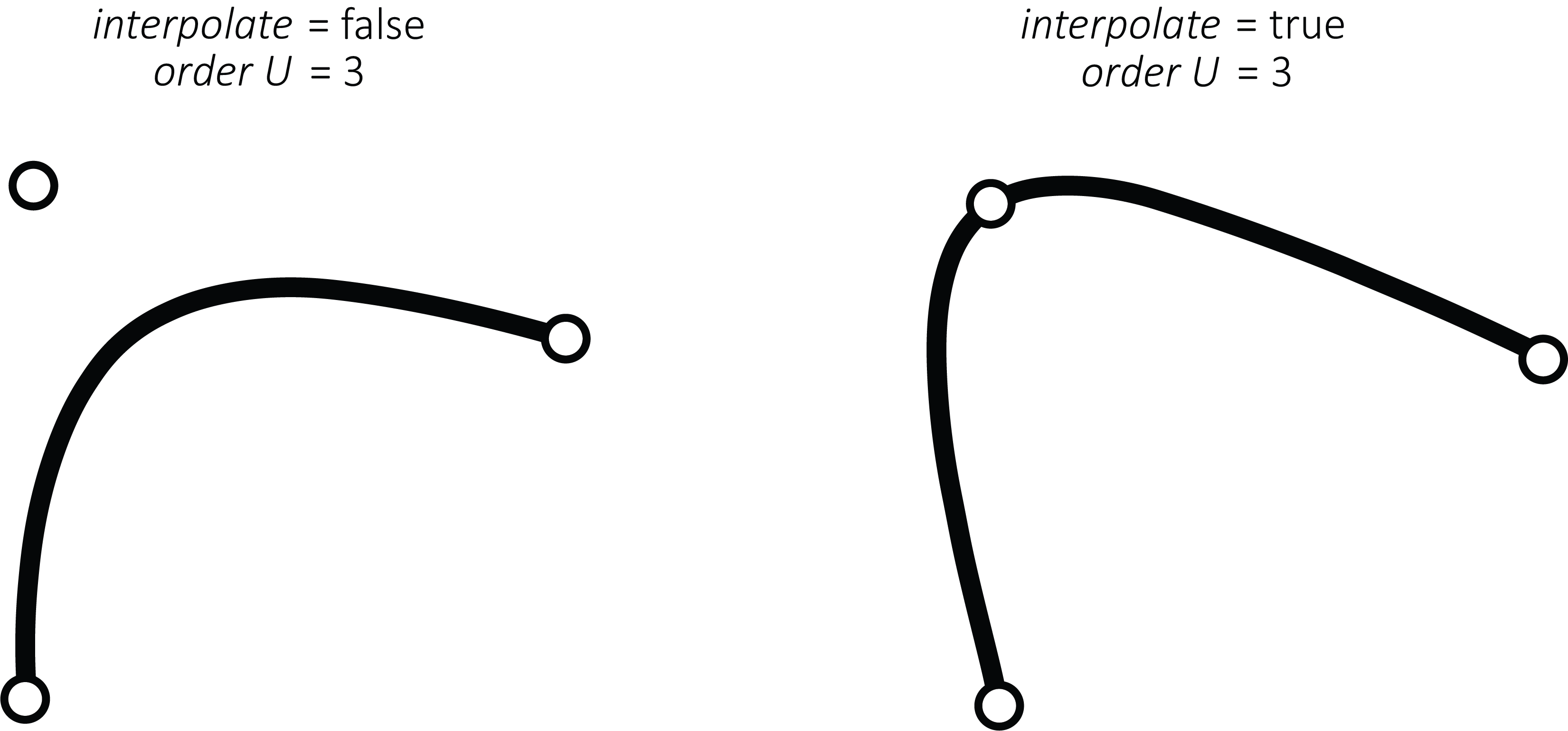
- Other names for this node include: Skin, and Revolve.
Examples
Split Surface
Splits NURBS surfaces along a U or V value.
Inputs
-
geometry
- Accepts a single geometry connection (unless the SHIFT key is held).
-
direction
- Sets the direction within which to split the surface. This can be
UorV.
- Sets the direction within which to split the surface. This can be
-
location
- The value at which to split the surface. Accepts values from
0-1.
- The value at which to split the surface. Accepts values from
-
discard
- Sets the calculated primitive to delete. This can be
none,first, orsecond.
- Sets the calculated primitive to delete. This can be
Outputs
-
geometry
- Output primitives.
-
points
- The list of points of the output primitives.
-
points.x
- The list of x values of the points of the output primitives.
-
points.y
- The list of y values of the points of the output primitives.
-
points.z
- The list of z values of the points of the output primitives.
Note(s)
- Other names for this node include: SplitPatch, Split patch, Cut, Nurbs, Carve.
Example(s)
Triangulate surface
Converts NURBS surfaces to meshes.
Inputs
-
geometry
- Accepts a single geometry connection (unless the SHIFT key is held).
-
mode
- Sets the mode in which the quality of the resulting triangulated mesh is determined. This can be
combine U & V qualityorseparate U & V quality.
- Sets the mode in which the quality of the resulting triangulated mesh is determined. This can be
-
quality
- The value that defines the quality for both U & V coordinates of the resulting triangulated mesh when mode is set to
combine U & V quality.
- The value that defines the quality for both U & V coordinates of the resulting triangulated mesh when mode is set to
-
qualityU
- The value that defines the quality for the U coordinate of the resulting triangulated mesh when mode is set to
separate U & V quality.
- The value that defines the quality for the U coordinate of the resulting triangulated mesh when mode is set to
-
qualityV
- The value that defines the quality for the U coordinate of the resulting triangulated mesh when mode is set to
separate U & V quality.
- The value that defines the quality for the U coordinate of the resulting triangulated mesh when mode is set to
Outputs
-
geometry
- Output primitives.
-
points
- The list of points of the output primitives.
-
points.x
- The list of x values of the points of the output primitives.
-
points.y
- The list of y values of the points of the output primitives.
-
points.z
- The list of z values of the points of the output primitives.
Note(s)
- Other names for this node include: TesselatePatch, NURBS to polygon, NURBS patch to triangles, Mesh, Tessellate, and Convert.
Example(s)
Clean mesh
Attempts to clean up "dirty" polygonal geometry.
Inputs
-
geometry
- Accepts a single geometry connection (unless the SHIFT key is held).
-
nuke small triangles
- Sets whether to delete small triangles or not. The area of the nuked triangles is set by the area threshold input.
-
area threshold
- The minimum area that determines if a triangle is nuked when nuke small triangles is set to
true.
- The minimum area that determines if a triangle is nuked when nuke small triangles is set to
-
nuke orphan points
- Sets whether to delete points not associated with any triangles or not.
Outputs
-
geometry
- Output primitives.
-
points
- The list of points of the output primitives.
-
points.x
- The list of x values of the points of the output primitives.
-
points.y
- The list of y values of the points of the output primitives.
-
points.z
- The list of z values of the points of the output primitives.
Note(s)
- Other names for this node include: PolyClean, Delete zero area, and Clean poly.
Example(s)
Combine meshes
Combines meshes into a single mesh.
Inputs
-
geometry
- Accepts multiple geometry connections.
-
group behavior
- Sets how input groups will behave. This can be
exclude meshes from groups(will not combine meshes within input groups),include meshes from groups(will combine meshes within all input groups), orcombine per top-level group(will only combine meshes within each input group).
- Sets how input groups will behave. This can be
Outputs
-
geometry
- Output primitives.
-
points
- The list of points of the output primitives.
-
points.x
- The list of x values of the points of the output primitives.
-
points.y
- The list of y values of the points of the output primitives.
-
points.z
- The list of z values of the points of the output primitives.
Notes
-
If you wish to treat multiple primitives as a single primitive (whilst preserving individual primitives), use the group and ungroup nodes.
-
This node is a destructive operation if there are more than one primitive in it's geometry input.
-
If the input meshes have different material properties, the combined mesh will take on the properties of the last input mesh primitive.
-
Other names for this node include: CombineMeshes, Merge meshes, Unify meshes, and Join.
Examples
Extrude mesh
Extrude all input faces.
Inputs
-
geometry
- Accepts a single geometry connection (unless the SHIFT key is held).
-
distance
- The distance input faces will be extruded by.
-
keep
- Sets which faces of the output primitives to keep. This can be
all( both the input faces as well as extruded faces and sides),sides,extruded cap(only the extruded faces),caps(only the input and extruded faces), orsides & extruded cap(the extruded sides and caps, but not the input faces).
- Sets which faces of the output primitives to keep. This can be
-
flip direction
- Sets whether to flip the direction of the extrusion.
-
flip normals
- Sets whether to flip the normals of the output primitives.
Outputs
-
points
- The list of points of the output primitives.
-
points.x
- The list of x values of the points of the output primitives.
-
points.y
- The list of y values of the points of the output primitives.
-
points.z
- The list of z values of the points of the output primitives.
Note(s)
-
Other names for this node include: Extrude.
Examples
Flip mesh normals
Flips the normals of all input polygons.
Inputs
-
geometry
- Accepts a single geometry connection (unless the SHIFT key is held).
Outputs
-
geometry
- Output primitives.
-
points
- The list of points of the output primitives.
-
points.x
- The list of x values of the points of the output primitives.
-
points.y
- The list of y values of the points of the output primitives.
-
points.z
- The list of z values of the points of the output primitives.
Note(s)
- Other names for this node include: ReverseMesh, Reverse Mesh, and Invert.
Example(s)
Mesh boundary
Creates polyline curves around all mesh boundaries.
Inputs
-
geometry
- Accepts a single geometry connection (unless the SHIFT key is held).
Outputs
-
geometry
- Output primitives.
-
points
- The list of points of the output primitives.
-
points.x
- The list of x values of the points of the output primitives.
-
points.y
- The list of y values of the points of the output primitives.
-
points.z
- The list of z values of the points of the output primitives.
-
boundary mask
- The list of boolean values identifying if a vertex was used to create a curve or not.
-
boundary indices
- The list of indices of the vertexes that define the resulting boundary.
Note(s)
-
An example of an instance where a mesh boundary will not be made (and therefore will turn a
falseresult in the boolean mask output) might be where mesh edges/boundaries are welded together (and thus not a boundary) or, a primitive type other than a PolyMesh is input into this node. -
Other names for this node include: MeshBoundary, Edges, Contour, and Border.
Example(s)
Unweld vertices
Splits shared triangle vertices on polygonal meshes.
Inputs
-
geometry
- Accepts a single geometry connection (unless the SHIFT key is held).
Outputs
-
geometry
- Output primitives.
-
points
- The list of points of the output primitives.
-
points.x
- The list of x values of the points of the output primitives.
-
points.y
- The list of y values of the points of the output primitives.
-
points.z
- The list of z values of the points of the output primitives.
Notes
-
Other names for this node include: UnweldVertices, Hard edges, and Facet.
Examples
Weld Vertices
Welds overlapping polygon triangle edges based on an angle threshold.
Inputs
-
geometry
- Accepts a single geometry connection (unless the SHIFT key is held).
-
radius
- The radius that determines if adjacent vertices will be welded together.
-
angle threshold
- The minimum angle that determines if adjacent vertices will be welded together.
-
average position
- Sets whether to average the position of welded vertices or not.
-
nuke ghost triangles
- Sets whether to delete triangles with zero area (that can often occur by the weld). This is done after the weld.
-
nuke orphan points
- Sets whether to delete points not associated with any triangles. This is done after the weld.
-
mask
- The list of boolean values that defines which vertices to weld together. If empty, all vertices will be welded together.
Outputs
-
geometry
- Output primitives.
-
points
- The list of points of the output primitives.
-
points.x
- The list of x values of the points of the output primitives.
-
points.y
- The list of y values of the points of the output primitives.
-
points.z
- The list of z values of the points of the output primitives.
Notes
- Other names for this node include: WeldVertices, Smooth normals, Merge points, and Weld polygons.
Examples
Triangulate 2d path
Converts 2D curves into a triangulated mesh in a chosen workplane.
Inputs
-
geometry
- Accepts a single geometry connection (unless the SHIFT key is held).
-
work plane
- The work plane in which the triangulation will be performed in. This can be
X=0,Y=0, orZ=0.
- The work plane in which the triangulation will be performed in. This can be
-
pre-flatten
- Flattens the input curves into the work plane defined by the work plane input before triangulation.
-
library
- Sets the triangulation library to triangulate input curves. This can be
Poly2Tri(quicker) orTriangle(slower, but offers triangle refinement and smoothing).
- Sets the triangulation library to triangulate input curves. This can be
-
input handling
- Sets how the input curves are handled within the triangulation. This can be
first curve is outline, others are holes(the first input curve is the outline and following input curves are holes within the resulting mesh) orall curves are outlines(all input curves are outlines and no holes are made).
- Sets how the input curves are handled within the triangulation. This can be
-
make convex hull
- Sets whether the resulting triangulation is a convex hull of the input curves or not.
-
algorithm
- Sets the algorithm to use for triangulation while the library input is set to
Triangle. This can besweepline,Dwyer, orincremental.
- Sets the algorithm to use for triangulation while the library input is set to
-
refine
- Sets whether or not to manually refine the triangles in the resulting triangulation when the library input is set to
Triangle.
- Sets whether or not to manually refine the triangles in the resulting triangulation when the library input is set to
-
max area
- The maximum area of triangles in the resulting triangulation when the library input is set to
Triangleand the refine input is set totrue.
- The maximum area of triangles in the resulting triangulation when the library input is set to
-
min angle
- The minimum angle of triangles in the resulting triangulation when the library input is set to
Triangleand the refine input is set totrue.
- The minimum angle of triangles in the resulting triangulation when the library input is set to
-
max angle
- The maximum angle of triangles in the resulting triangulation when the library input is set to
Triangleand the refine input is set totrue.
- The maximum angle of triangles in the resulting triangulation when the library input is set to
-
smoothing
- The amount of smoothing of triangle layout after triangulation defined between
0and100.
- The amount of smoothing of triangle layout after triangulation defined between
-
inner points
- A list of extra internal points that will force the creation of vertices at these points.
Outputs
-
geometry
- Output primitives.
-
points
- The list of points of the output primitives.
-
points.x
- The list of x values of the points of the output primitives.
-
points.y
- The list of y values of the points of the output primitives.
-
points.z
- The list of z values of the points of the output primitives.
Notes
-
The
first curve is outline, others are holessetting of the input handling input results in a single primitive whereas theall curves are outlinessetting results in a primitive for each input curve. -
If the input curve is irregular and the resulting triangulate mesh results in “zero area triangles”, it is recommended to use the Clean mesh node to fix the mesh.
-
Other names for this node include: TriangulateCurve, Triangulate curve, Tessellate, Mesh, and Path to mesh.
Examples
Delete points
Deletes points using a mask or index list.
Inputs
-
geometry
- Accepts a single geometry connection (unless the SHIFT key is held).
-
mask
- The list of boolean values that defines which points to delete from input primitives.
-
index list
- The list of indices that defines which points to delete from input primitives.
-
invert
- Sets whether to invert the selection of deleted points or not.
Outputs
-
geometry
- Output primitives.
-
points
- The list of points of the output primitives.
-
points.x
- The list of x values of the points of the output primitives.
-
points.y
- The list of y values of the points of the output primitives.
-
points.z
- The list of z values of the points of the output primitives.
Note(s)
-
This node will delete points from almost any input primitives with some exceptions:
-
Polylines/NURBS curves where the resulting curve will be left with only a single point.
-
Other names for this node include: DeletePoints, Erase, and Nuke.
Example(s)
Get Points
Gets the points of input primitives using a mask.
Inputs
-
geometry
- Accepts a single geometry connection (unless the SHIFT key is held).
-
mask
- The boolean list that defines which points to keep and which points to discard.
Outputs
-
geometry
- Output points primitive.
-
points
- The list of points of the output points primitive.
-
points.x
- The list of x values of the points of the output primitives.
-
points.y
- The list of y values of the points of the output primitives.
-
points.z
- The list of z values of the points of the output primitives.
Note(s)
- Other names for this node include: ExtractPoints, Extract points, Isoparm, and NURBS.
Example(s)
Set point weight
Sets point weights.
Inputs
-
geometry
- Accepts a single geometry connection (unless the SHIFT key is held).
-
weights
-
default weight
- The weight value that defines the weight of all points when no data is connected to the weights input.
Outputs
-
geometry
- Output primitives.
-
points
- The list of points of the output primitives.
-
points.x
- The list of x values of the points of the output primitives.
-
points.y
- The list of y values of the points of the output primitives.
-
points.z
- The list of z values of the points of the output primitives.
Note(s)
-
Sets the weight value of input geometry points based on input data values for use in NURBS curves and surfaces.
-
The weight value’s effect exhibits an exponential decay pattern as the ratio between points increases. For example, the difference between a weight ratio of
0and2is less than twice the difference between a weight ratio of0and1.- For more information on NURBS curve point weights, see: NURBS curves
-
If default weight is in use all points will have the same weight so the exact value is irrelevant unless set to
0in which case no geometry will be generated. -
Other names for this node include: SetPointWeight, Edit point weight, and Weight.
Example(s)
Set points
Sets the position of points using xyz values.
Inputs
-
geometry
- Accepts a single geometry connection (unless the SHIFT key is held).
-
x
- The x value of the vector position to set input points to.
-
y
- The y value of the vector position to set input points to.
-
z
- The z value of the vector position to set input points to.
-
mask
- The list of boolean values that defines which input points to set to the vector as defined by the x, y, and z inputs. If empty, all input points will be set to the defined vector.
Outputs
-
geometry
- Output primitives.
-
points
- The list of points of the output primitives.
-
points.x
- The list of x values of the points of the output primitives.
-
points.y
- The list of y values of the points of the output primitives.
-
points.z
- The list of z values of the points of the output primitives.
Notes
- Other names for this node include: SetPoints, and Set positions.
Examples
Delete primitives
Deletes primitives using a mask or index list.
Inputs
-
geometry
- Accepts a single geometry connection (unless the SHIFT key is held).
-
mask
- The list of boolean values that defines which primitives to delete.
-
index list
- The list of indices that defines which primitives to delete.
-
invert
- Sets whether to invert the selection of deleted primitives or not.
-
keep points
- Sets whether to keep the points of deleted primitives or not.
Outputs
-
geometry
- Output primitives.
-
points
- The list of points of the output primitives.
-
points.x
- The list of x values of the points of the output primitives.
-
points.y
- The list of y values of the points of the output primitives.
-
points.z
- The list of z values of the points of the output primitives.
Note(s)
- Other names for this node include: DeletePrimitives, Erase, and Nuke.
Example(s)
Get primitive
Gets primitives using input indices.
Inputs
-
geometry
- Accepts a single geometry connection (unless the SHIFT key is held).
-
index
- The index value that defines which primitive to get/output from the list of input primitives.
-
invert
- Sets whether to invert the selection of output primitives or not.
Outputs
-
geometry
- Output primitives.
-
points
- The list of points of the output primitives.
-
points.x
- The list of x values of the points of the output primitives.
-
points.y
- The list of y values of the points of the output primitives.
-
points.z
- The list of z values of the points of the output primitives.
Note(s)
- Other names for this node include: GetPrimitive, Delete, Isolate, and Choose.
Example(s)
Group
Groups primitives into a “group” primitive type.
Inputs
-
geometry
- Accepts multiple geometry connections.
-
group name
- The name to give to the group made by the node.
Outputs
-
geometry
- Output primitives.
-
points
- The list of points of the output primitives.
-
points.x
- The list of x values of the points of the output primitives.
-
points.y
- The list of y values of the points of the output primitives.
-
points.z
- The list of z values of the points of the output primitives.
Notes
-
Group primitives can be ungrouped with the ungroup node.
-
Other names for this node include: GroupPrimitives, Group primitives, and Assemble.
Examples
Ungroup
Ungroups “group” primitives.
Inputs
-
geometry
- Accepts a single geometry connection (unless the SHIFT key is held).
-
mode
- Sets the mode in which group primitives are ungrouped. This can be
flatten whole hierarchy(which ungroups all groups, even groups within other groups) orungroup one level(which only ungroups the first layer of groups, any group within another group is not ungrouped).
- Sets the mode in which group primitives are ungrouped. This can be
Outputs
-
geometry
- Output primitives.
-
points
- The list of points of the output primitives.
-
points.x
- The list of x values of the points of the output primitives.
-
points.y
- The list of y values of the points of the output primitives.
-
points.z
- The list of z values of the points of the output primitives.
Notes
-
Primitives can be grouped together with the group node.
-
Other names for this node include: UngroupPrimitives, Ungroup primitives, Disassemble, and Split group.
Examples
Reverse primitive list
Reverses the order of primitives.
Inputs
-
geometry
- Accepts a single geometry connection (unless the SHIFT key is held).
Outputs
-
geometry
- Output primitives.
-
points
- The list of points of the output primitives.
-
points.x
- The list of x values of the points of the output primitives.
-
points.y
- The list of y values of the points of the output primitives.
-
points.z
- The list of z values of the points of the output primitives.
Note(s)
- Other names for this node include: ReversePrimitiveList.
Example(s)
Shift primitive list
Shifts the primitive order.
Inputs
-
geometry
- Accepts a single geometry connection (unless the SHIFT key is held).
Outputs
-
geometry
- Output primitives.
-
points
- The list of points of the output primitives.
-
points.x
- The list of x values of the points of the output primitives.
-
points.y
- The list of y values of the points of the output primitives.
-
points.z
- The list of z values of the points of the output primitives.
Note(s)
- Other names for this node include: ShiftPrimitiveList.
Example(s)
Boolean 3D geometry
Performs boolean operations on 3D geometry.
Inputs
-
geometry
- Accepts multiple geometry connections.
-
operation type
- Sets the type of boolean operation to perform on input geometry. This can be:
Union,Subtraction,Reverse subtraction,Intersection, orXOR.
- Sets the type of boolean operation to perform on input geometry. This can be:
-
weld
- Sets whether to pre-weld input geometry or not.
Outputs
-
geometry
- Output primitives.
-
points
- The list of points of the output primitives.
-
points.x
- The list of x values of the points of the output primitives.
-
points.y
- The list of y values of the points of the output primitives.
-
points.z
- The list of z values of the points of the output primitives.
Note(s)
-
This node specifically operates on PolyMesh type primitives. Therefore there are a couple things to keep in mind to get consistent results when using this node:
-
Avoid coplanar faces
- Specifically this means geometry that is being operated on has faces that are within the same plane as each other (one example may be when unioning two boxes that have been aligned directly next to each other, where one side of each box touches a side of another). Often stretching an input geometry (with either the transform or smart size nodes) so that there is a clear overlap, can help with more consistent behavior.
-
Edges and vertices,
- A mesh 3D boolean operation utilizes vertices and edges of input meshes to perform operations. Therefore, it is often useful to pay attention to where particular geometries are positioned. Say for example we have a box that is subtracting from another box where the position of the subtracting box is positioned so that it lies directly in the middle of a triangle of the first box's mesh. In this instance, there are no intersecting edges or vertices of either mesh, thus making it difficult to calculate consistently.
-
-
This node is a destructive operation.
-
Other names for this node include: MeshBoolean, Mesh boolean, 3D boolean, and CSG.
Example(s)
Align
Aligns input primitives to each other.
Inputs
-
geometry
- Accepts multiple geometry connections.
-
mode
- Sets the mode in which input primitives are aligned. This can be
between primitive connections(which will align input geometry to the primitives within the first geometry connection) orall input primitives(which will align input geometry to the first primitive).
- Sets the mode in which input primitives are aligned. This can be
-
x align target
- Sets what boundary/value that primitives are aligned by in the x-axis. This can be
None(which will not align primitives in the x-axis),min,centroid, ormax.
- Sets what boundary/value that primitives are aligned by in the x-axis. This can be
-
x source
- Sets what source that primitives are aligned to in the x-axis. This can be
first connection or primitive(as defined by the mode input),average of all(which takes the bounds of all input primitives), orvalue(which aligns to a particular value rather than the bounds of primitives).
- Sets what source that primitives are aligned to in the x-axis. This can be
-
of x source
- Sets what boundary/value that primitives are aligned to in the x-axis. This can be
min,centroid, ormax.
- Sets what boundary/value that primitives are aligned to in the x-axis. This can be
-
x value
- The value that primitives are aligned to in the x-axis when the x source input is set to
value.
- The value that primitives are aligned to in the x-axis when the x source input is set to
-
x offset
- The value that defines how much to offset primitives from the alignment in the x-axis.
-
y align target
- Sets what boundary/value that primitives are aligned by in the y-axis. This can be
None(which will not align primitives in the y-axis),min,centroid, ormax.
- Sets what boundary/value that primitives are aligned by in the y-axis. This can be
-
y source
- Sets what source that primitives are aligned to in the y-axis. This can be
first connection or primitive(as defined by the mode input),average of all(which takes the bounds of all input primitives), orvalue(which aligns to a particular value rather than the bounds of primitives).
- Sets what source that primitives are aligned to in the y-axis. This can be
-
of y source
- Sets what boundary/value that primitives are aligned to in the y-axis. This can be
min,centroid, ormax.
- Sets what boundary/value that primitives are aligned to in the y-axis. This can be
-
y value
- The value that primitives are aligned to in the y-axis when the y source input is set to
value.
- The value that primitives are aligned to in the y-axis when the y source input is set to
-
y offset
- The value that defines what to offset primitives from the alignment in the y-axis.
-
z align target
- Sets what boundary/value that primitives are aligned by in the z-axis. This can be
None(which will not align primitives in the z-axis),min,centroid, ormax.
- Sets what boundary/value that primitives are aligned by in the z-axis. This can be
-
z source
- Sets what source that primitives are aligned to in the z-axis. This can be
first connection or primitive(as defined by the mode input),average of all(which takes the bounds of all input primitives), orvalue(which aligns to a particular value rather than the bounds of primitives).
- Sets what source that primitives are aligned to in the z-axis. This can be
-
of z source
- Sets what boundary/value that primitives are aligned to in the z-axis. This can be
min,centroid, ormax.
- Sets what boundary/value that primitives are aligned to in the z-axis. This can be
-
z value
- The value that primitives are aligned to in the z-axis when the z source input is set to
value.
- The value that primitives are aligned to in the z-axis when the z source input is set to
-
z offset
- The value that defines what to offset primitives from the alignment in the z-axis.
-
first object
- Sets what to do with the first geometry connection/primitive. This can be
keep position,include in align, ordelete.
- Sets what to do with the first geometry connection/primitive. This can be
Outputs
-
geometry
- Output primitives.
-
points
- The list of points of the output primitives.
-
points.x
- The list of x values of the points of the output primitives.
-
points.y
- The list of y values of the points of the output primitives.
-
points.z
- The list of z values of the points of the output primitives.
Note(s)
- When the mode input is set to
between primitive connectionsthe primitives in each input geometry connection are treated as a group.
Examples
Mirror
Mirrors geometry across a selected axis.
Inputs
-
geometry
- Accepts a single geometry connection (unless the SHIFT key is held).
-
axis
- Sets the axis in which input primitives are mirrored across. This can be
x,y, orz.
- Sets the axis in which input primitives are mirrored across. This can be
-
mode
- Sets the position of the mirror axis in which input primitives are mirrored. This can be
around min,around center,around max, oraround pivot value(which sets a custom mirror axis).
- Sets the position of the mirror axis in which input primitives are mirrored. This can be
-
pivot
- The vector value that defines the mirror plane when the mode input is set to
around pivot value.
- The vector value that defines the mirror plane when the mode input is set to
-
keep input geo
- Sets whether to keep the input primitives or not.
-
combine result
- Sets how resulting meshes are combined. This can be
leave as is(will not combine meshes),combine pairs of meshes(will combine an individual PolyMesh primitive with its mirrored pair), orcombine all meshes.
- Sets how resulting meshes are combined. This can be
-
mask
- The list of boolean values that defines which primitives to mirror. If empty, all primitives will be mirrored.
Outputs
-
geometry
- Output primitives.
-
points
- The list of points of the output primitives.
-
points.x
- The list of x values of the points of the output primitives.
-
points.y
- The list of y values of the points of the output primitives.
-
points.z
- The list of z values of the points of the output primitives.
Note(s)
-
The mode inputs first three options (
around min,around center, andaround max) set the mirror axis position at the bounds of the input primitives. -
Mirrored primitives will also have their UV’s (NURBS curves and surfaces) and normals mirrored as well.
Example(s)
Smart size
Rescales geometry while preserving features within set zones.
Inputs
-
geometry
- Accepts a single geometry connection (unless the SHIFT key is held).
-
axis
- Sets the axis in which input primitives are scaled. This can be
x,y, orz.
- Sets the axis in which input primitives are scaled. This can be
-
size
- The size in which input primitives are scaled to.
-
reset size
- Resets the size input back to the input primitives original size.
-
scale around
- Sets the bounds which input primitives are scaled around. This can be
min,center, andmax.
- Sets the bounds which input primitives are scaled around. This can be
-
lower lock zone
- The lower lock zone coordinate (0 to 1) in which input primitive features are preserved.
-
upper lock zone
- The upper lock zone coordinate (0 to 1) in which input primitive features are preserved.
-
mask
- A list of boolean values that defines which input primitive points are scaled. If empty, all input primitive points will be scaled.
Outputs
-
geometry
- Output primitives.
-
points
- The list of points of the output primitives.
-
points.x
- The list of x values of the points of the output primitives.
-
points.y
- The list of y values of the points of the output primitives.
-
points.z
- The list of z values of the points of the output primitives.
Note(s)
- The scaling operation of the node works by only scaling the parts of the input primitives that are not within the range as defined by the upper and lower lock zones. The parts of the input geometry that are outside of the specified range will have their features preserved.
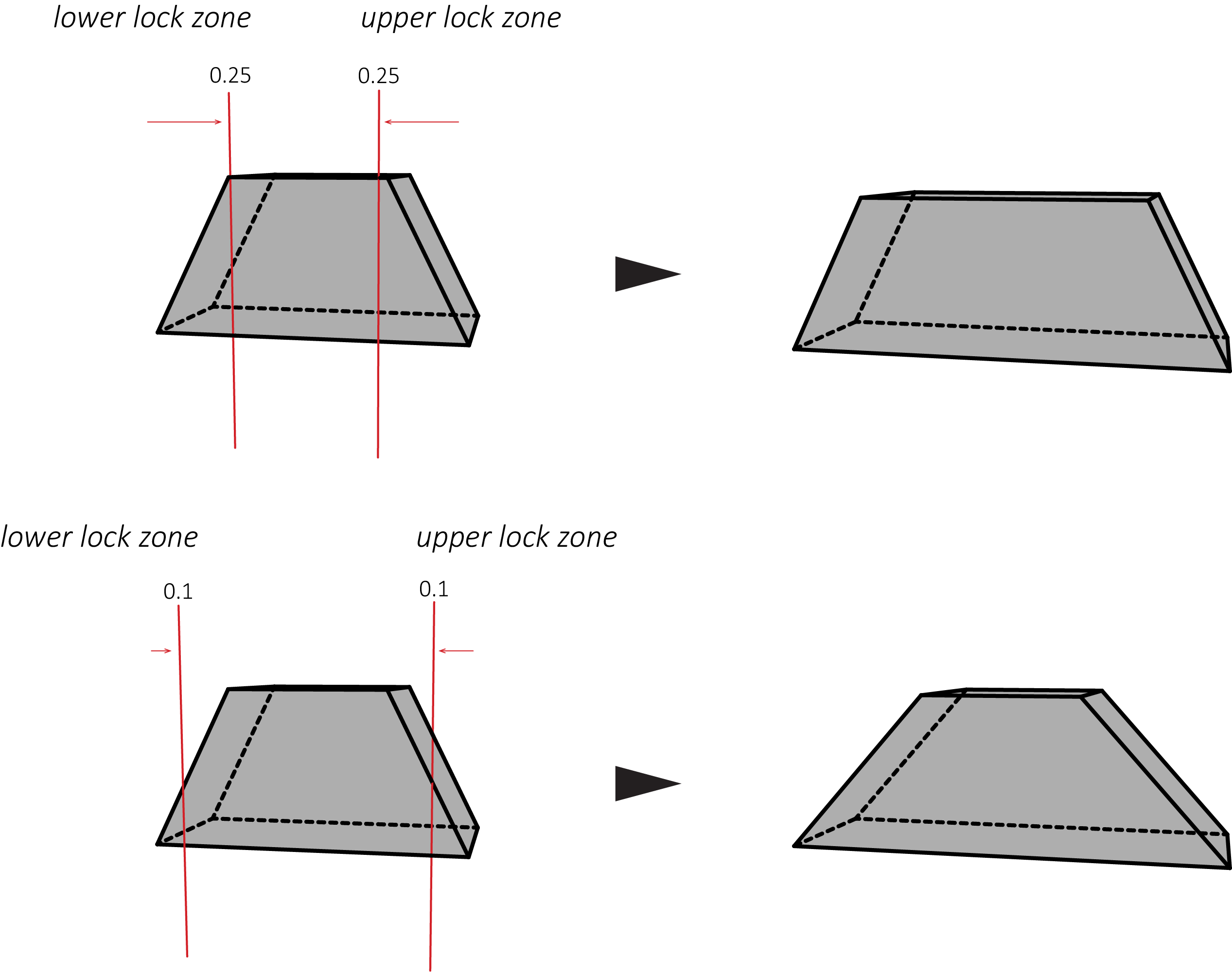
-
The lock zones are specified as a percentage (0 to 1) of the input primitives bounds. The lower lock zone is taken from the minimum bounds of the axis specified by the axis input, whereas the upper lock zone is taken from the maximum bounds.
- Therefore the sum of both the upper and lower lock zones cannot be greater or equal to
1so that these zones do not overlap.
- Therefore the sum of both the upper and lower lock zones cannot be greater or equal to
-
Other names for this node include: SmartSize.
Example(s)
Transform
Performs transformations (translate, rotate, and scale) on geometry.
Inputs
-
geometry
- Accepts multiple geometry connections.
-
translate
- The vector value that defines the translation input primitives will move.
-
rotate
- The vector value that defines the rotation input primitives will rotate around based on the center pivot or pivot inputs.
-
scale
- The vector value that defines how much the input primitives will be scaled by.
-
center pivot
- Sets whether the input primitives will be manipulated with respect to their centers or not.
-
pivot
- The vector value that defines the position of the pivot that the input primitives will be manipulated with respect to when the center pivot input is set to
false.
- The vector value that defines the position of the pivot that the input primitives will be manipulated with respect to when the center pivot input is set to
Outputs
-
geometry
- Output primitives.
-
points
- The list of points of the output primitives.
-
points.x
- The list of x values of the points of the output primitives.
-
points.y
- The list of y values of the points of the output primitives.
-
points.z
- The list of z values of the points of the output primitives.
-
translate
- The list of vector values that input primitives have been translated by.
-
rotate
- The list of vector values that input primitives have been rotated by.
-
scale
- The list of vector values that input primitives have been scaled by.
Note(s)
- Other names for this node include: TransfromPrimitives, Move, Translate, Rotate, Scale, Position, and Size.
Example(s)
Flip UV
Swaps or flips UV coordinates of NURBS surfaces. Reverses NURBS curves.
Inputs
-
geometry
- Accepts a single geometry connection (unless the SHIFT key is held).
-
mode
- Sets the mode in which the UV coordinates are manipulated. This can be
no change,flip U,flip V,flip U & V, orswap U & V.
- Sets the mode in which the UV coordinates are manipulated. This can be
-
mask
- The list of boolean values that defines which primitives to apply manipulations to as set by the mode.
Outputs
-
geometry
- Output primitives.
-
points
- The list of points of the output primitives.
-
points.x
- The list of x values of the points of the output primitives.
-
points.y
- The list of y values of the points of the output primitives.
-
points.z
- The list of z values of the points of the output primitives.
Note(s)
-
NURBS curves only have a U coordinate and will therefore only be affected by the
flip Uandflip U & Vmodes, effectively reversing the direction of the curve. -
Other names for this node include: FlipUV, Swap, and Reverse curve.
Example(s)
Get UV
Gets UVs from mesh points.
Inputs
-
default u
- The value to output if there are no U values on an input point.
-
default v
- The value to output if there are no V values on an input point.
Outputs
-
u
- The list of U values of the points within an input mesh.
-
v
- The list of V values of the points within an input mesh.
Note(s)
-
Currently only operates on PolyMesh primitives, not NURBS surfaces etc. If any primitive type other than a PolyMesh is input, the default u and default v values will be output.
-
Other names for this node include: ExtractUV, Extract UVs.
Example(s)
Collect
Collects all primitives from all geometry inputs into a single geometry output.
Inputs
-
geometry
- Accepts multiple geometry connections.
Outputs
-
geometry
- Output primitives.
-
points
- The list of points of the output primitives.
-
points.x
- The list of x values of the points of the output primitives.
-
points.y
- The list of y values of the points of the output primitives.
-
points.z
- The list of z values of the points of the output primitives.
Note(s)
- This node simply gathers incoming primitives into a list, arranging them in the order of their associated geometry input connections.
- Other names for this node include: Merge and Collate.
Example(s)
Null
Does nothing. Can be used for graph layout.
Inputs
-
geometry
- Accepts a single geometry connection (unless the SHIFT key is held).
Outputs
-
geometry
- Output primitives.
-
points
- The list of points of the output primitives.
-
points.x
- The list of x values of the points of the output primitives.
-
points.y
- The list of y values of the points of the output primitives.
-
points.z
- The list of z values of the points of the output primitives.
Note(s)
-
When geometry is input into this node, the exact same geometry will be output with no modifications.
-
There are two main uses for this node.
-
The first is where we can utilize its ability to output nothing. This can be useful in such cases where a graph can be configured to hide certain geometry of a final output (see the relevant example below).
-
The second is where we can utilize its ability to output the exact same geometry that is input. The can be helpful in such cases to clean a graph's layout (see the relevant example below).
-
-
Other names for this node include: Nothing, Layout, and Routing.
Example(s)
-
Isolate face holes & boundary (an example of the node being used for cleaner graph layout)
Switch
Switches between geometry inputs using an index value.
Inputs
-
geometry
- Accepts multiple geometry connections.
-
index
- The index of the geometry connection to output.
Outputs
-
geometry
- Output primitives.
-
points
- The list of points of the output primitives.
-
points.x
- The list of x values of the points of the output primitives.
-
points.y
- The list of y values of the points of the output primitives.
-
points.z
- The list of z values of the points of the output primitives.
Note(s)
-
A special function of the this node is that the graph will not compute geometry that isn't within the connection selected by the index input.
- As such, this node can be used to optimize the computation of the graph by switching between computationally light and heavy geometry with the Ephemeral State node.
- This is not true, however, for the Number switch, Vector switch, or String switch nodes.
-
Other names for this node include: Choose and Pick.
Example(s)
Closest value
Finds the closest value in a number list.
Inputs
-
source values
- The list of source values to find the closest values among the target values.
-
target values
- The list of target values among which the closest values are found from the source values.
Outputs
-
value
- The closest value from the target values to the source values.
-
value list
- The list of closest values from the target values to the source values.
-
target indices
- The list of the indices of the found closest values from the target values list.
-
deltas
- The list of differences between the source values and their found closest target values.
Note(s)
- Other names for this node include: ClosestValue, Nearest value, Distance, Delta, and Difference.
Example(s)
Combine number lists
Joins number lists.
Inputs
-
list 1
- The first list of values to combine.
-
list 2
- The second list of values to combine.
-
list 3
- The third list of values to combine.
-
list 4
- The fourth list of values to combine.
Outputs
-
list
- The combined list as defined by the list 1, list 2, list 3, and list 4 inputs.
Note(s)
-
Chain multiple combine number list nodes together to combine more than four number lists.
-
Other names for this node include: CombineLists, Append, Concatenate, Merge, and Join.
Example(s)
Cull number lists
Cull a number list using a mask.
Inputs
-
list
- The list of values to cull.
-
mask
- The list of boolean values that defines which values to cull.
Outputs
-
list
- The list of values after defined values have been culled.
-
reject list
- The list of values that have been culled.
Note(s)
- Other names for this node include: CullList, Split list.
Example(s)
Get number list item
Gets the value of an item in a number list.
Inputs
-
list
- The list of values to get a list item from.
-
index
- The index value that defines which list item to get from the list input.
Outputs
-
value
- The value of the gotten list item.
-
value list
- The list of values of gotten list items.
Note(s)
-
Multiple list items can be gotten by inputting a list of indices into the index input.
-
Other names for this node include: GetListItem, Switch, Choose, Pick, Choice, or List item.
Example(s)
Match number lists
Checks the commonality between two number lists.
Inputs
-
list 1
- The first list to match against.
-
list 2
- The second list to match against.
Outputs
-
list 1 matches
- The list of booleans signaling whether the value at a particular index in list 1 matches any value within list 2.
-
list 2 matches
- The list of booleans signaling whether the value at a particular index in list 2 matches any value within list 1.
Note(s)
-
This node returns two lists of booleans, one for each input list (same length) - items are true if the number at their index is found in the other list.
-
Other names for this node include: MatchNumberLists.
Example(s)
Reverse number list
Reverses a number list.
Inputs
-
list
- The list of values to reverse.
Outputs
-
list
- The reversed list of values.
Note(s)
- Other names for this node include: ReverseList.
Example(s)
- No particular examples at this time. Check back later!
Set number list item
Sets an item's value in a number list.
Inputs
-
list
- The list of values to set a list item within.
-
index
- The index value that defines which list item to set from the list input.
-
value
- The value that defines what to set the list item’s value to.
Outputs
-
list
- The edited list of values.
Note(s)
- Other names for this node include: SetListItem.
Example(s)
Set number list items
Sets multiple item values in a number list.
Inputs
-
list
- The list of values to set list items within.
-
indexList
- The list of index values that defines which list items to set from the list input.
-
values
- The value that defines what to set the list item’s values to.
Outputs
-
list
- The edited list of values.
Note(s)
- Other names for this node include: SetListItems.
Example(s)
Shift number list
Shifts the items of a number list.
Inputs
-
list
- The list of values to shift.
-
shift
- The value that defines the number of positions to shift the list.
Outputs
-
list
- The shifted list of values.
Note(s)
-
A shifted list is cyclic.
- For example, if a list is shifted by a shift input value of
-1, the value at index0is now at index1and the value that was at the end of the list is now at index0.
- For example, if a list is shifted by a shift input value of
-
Other names for this node include: ShiftList.
Example(s)
Shuffle number list
Shuffles the items of a number list.
Inputs
-
list
- The list of values to shuffle.
Outputs
-
list
- The shuffled list of values.
Note(s)
-
This node will shuffle the input list each time it is computed. In other words, it will re-shuffle the input list whenever the input list changes, a node upstream of it has changed (even if the values in the list itself seems to stay the same), or the graph is re-loaded.
-
Other names for this node include: ShuffleList, Randomize, and Randomise.
Example(s)
Sort number list
Sorts the values of a number list.
Inputs
-
list
- The list of values to sort.
-
near value
- The value that is used to find the closest value to it (above and below) in the list input.
Outputs
-
sorted list
- The sorted list of values.
-
original indexes
- The list of original indexes in the order of the sorted list.
-
reverse indexes
- The list of sorted indexes in the order of the original list.
-
value below
- The value immediately below the value defined by the near value input in the sorted list.
-
value above
- The value immediately above the value defined by the near value input in the sorted list.
-
below index
- The index value of the value below output.
-
above index
- The index value of the value above output.
Note(s)
-
This can also be used to find the closest values to an input value from within a sorted list by using the near value input and the value below, value above, below index, and above index outputs.
-
Other names for this node include: SortFloatList.
Example(s)
Combine string lists
Joins string lists.
Inputs
-
list 1
- The first list of string values to combine.
-
list 2
- The second list of string values to combine.
-
list 3
- The third list of string values to combine.
-
list 4
- The fourth list of string values to combine.
Outputs
-
list
- The combined string list as defined by the list 1, list 2, list 3, and list 4 inputs.
Note(s)
-
Chain multiple combine string list nodes together to combine more than four string lists.
-
Other names for this node include: CombineStringLists, Append, Concatenate, and Merge.
Example(s)
Cull string list
Culls a string list using a mask.
Inputs
-
list
- The list of strings to cull.
-
mask
- The list of boolean values that defines which strings to cull.
Outputs
-
list
- The list of strings after defined values have been culled.
-
reject list
- The list of strings that have been culled.
Note(s)
- Other names for this node include: CullStringList.
Example(s)
Find in string list
Searches for a string in a string list.
Inputs
-
list
- The list of string values in which to find the search string.
-
search string
- The string value to find in the string list.
-
index offset
- The value which defines how much to offset output indices.
Outputs
-
found
- The boolean value signaling whether a string was found or not.
-
first hit index
- The index of the first found string value in the list.
-
all hit indices
- The list indices of all found strings within the list.
Note(s)
- Other names for this node include: FindInStringList, Search, and Compare.
Example(s)
- Find particular primitives within a random batch of primitives (w/ attributes)
Get string list item
Gets a string from a string list using an index value.
Inputs
-
list
- The list of strings to get a list item from.
-
index
- The index value that defines which list item to get from the list input.
Outputs
-
string
- The string of the gotten list item.
-
string list
- The list of strings of gotten list items.
Note(s)
-
Multiple list items can be gotten by inputting a list of indices into the index input.
-
Other names for this node include: GetStringListItem, Switch, Choose, Pick, Choice, or List item.
Example(s)
Reverse string list
Reverses a string list.
Inputs
-
list
- The list of string values to reverse.
Outputs
-
list
- The reversed list of string values.
Note(s)
- Other names for this node include: ReverseStringList.
Example(s)
- No particular examples at this time. Check back later!
Set string list item
Sets a string's value in a string list.
Inputs
-
list
- The list of strings to set a list item within.
-
index
- The index value that defines which list item to set from the list input.
-
text
- The string that defines what to set the list item’s value to.
Outputs
-
list
- The edited list of strings.
Note(s)
- Other names for this node include: SetStringListItem.
Example(s)
String list to string
Concatenates a string list to a string.
Inputs
-
list
- The list of strings to concatenate.
-
separator
- The string that will separate the concatenated string list items (typically a comma
,).
- The string that will separate the concatenated string list items (typically a comma
Outputs
-
string
- The concatenated string list.
Note(s)
-
To concatenate means to “put in series” or to “chain”. Therefore to concatenate a string list is to “chain” a string list into a single string, separated by a separator.
-
Other names for this node include: StringListToString, Concatenate, or Join strings.
Example(s)
Combine vector lists
Joins vector lists.
Inputs
-
list 1
- The first list of vector values to combine.
-
list 2
- The second list of vector values to combine.
-
list 3
- The third list of vector values to combine.
-
list 4
- The fourth list of vector values to combine.
Outputs
-
list
- The combined vector list as defined by the list 1, list 2, list 3, and list 4 inputs.
Note(s)
-
Chain multiple combine vector list nodes together to combine more than four vector lists.
-
Other names for this node include: CombineVectorLists, Append, Concatenate, and Merge.
Example(s)
Cull vector list
Culls a vector list using a mask.
Inputs
-
list
- The list of vector values to cull.
-
mask
- The list of boolean values that defines which vector values to cull.
Outputs
-
list
- The list of vector values after defined vector values have been culled.
-
reject list
- The list of vectors values that have been culled.
Note(s)
- Other names for this node include: CullVectorList.
Example(s)
Get vector list item
Gets a vector from a vector list using an index value.
Inputs
-
list
- The list of vectors to get a list item from.
-
index
- The index value that defines which list item to get from the list input.
-
errorMode
- Sets how the node will behave when errored. This can be
error this nodeoroutput default vector.
- Sets how the node will behave when errored. This can be
-
default vector
- The default vector to output when the errorMode input is set to
output default vector.
- The default vector to output when the errorMode input is set to
Outputs
-
vector
- The vector of the gotten list item.
-
x
- The x value of the gotten list item vector.
-
y
- The y value of the gotten list item vector.
-
z
- The z value of the gotten list item vector.
-
vector list
- The list of vectors of gotten list items.
-
x list
- The list of x values of the gotten list items vectors.
-
y list
- The list of y values of the gotten list items vectors.
-
z list
- The list of z values of the gotten list items vectors.
Note(s)
-
Multiple list items can be gotten by inputting a list of indices into the index input.
-
Other names for this node include: GetVectorListItem, Switch, Choose, Pick, Choice, or List item.
Example(s)
Reverse vector list
Reverses a vector list.
Inputs
-
list
- The list of vector values to reverse.
Outputs
-
list
- The reversed list of vector values.
Note(s)
- Other names for this node include: ReverseVectorList.
Example(s)
Set vector list item
Sets the value of a vector in a vector list.
Inputs
-
list
- The list of vector values to set a list item within.
-
index
- The index value that defines which list item to set from the list input.
-
value
- The vector value that defines what to set the list item’s vector value to.
Outputs
-
list
- The edited list of vector values.
Note(s)
- Other names for this node include: SetVectorListItem.
Example(s)
Set vector list items
Sets multiple item values in a number list.
Inputs
-
list
- The list of values to set an item within.
-
indexList
- The list of index values that defines which items to set from the list input.
-
values
- The value that defines what to set the item’s values to.
Outputs
-
list
- The list of values with the item’s set values.
Note(s)
- Other names for this node include: SetVectorListItems.
Example(s)
Shift vector list
Shifts the items of a vector list.
Inputs
-
list
- The list of vector values to shift.
-
shift
- The value that defines the number of positions to shift the list.
Outputs
-
list
- The shifted list of vector values.
Note(s)
-
A shifted list is cyclic.
- For example, if a list is shifted by a shift input value of
-1, the vector value at index0is now at index1and the vector value that was at the end of the list is now at index0.
- For example, if a list is shifted by a shift input value of
-
Other names for this node include: ShiftVectorList.
Example(s)
Shuffle vector list
Shuffles a vector list.
Inputs
-
list
- The list of vector values to shuffle.
Outputs
-
list
- The shuffled list of vector values.
Note(s)
-
This node will shuffle the input vector list each time it is computed. In other words, it will re-shuffle the input vector list whenever the input vector list changes, a node upstream of it has changed (even if the values in the list itself seems to stay the same), or the graph is re-loaded.
-
Other names for this node include: ShuffleVectorList, Randomize, and Randomise.
Example(s)
List length
Calculates the number of items in a list.
Inputs
-
list
- The list of values to calculate the length of.
Outputs
-
length
- The length of the input list.
-
length minus one
- The length of the input list minus
1.
- The length of the input list minus
Note(s)
- Other names for this node include: ListLength, Count, and Size.
Example(s)
Absolute value
Returns the absolute value of a value.
Inputs
-
value
- The value that the absolute will be taken from.
Outputs
-
result
- The absolute value.
-
result list
- The list of absolute values.
Note(s)
-
The absolute value will always be positive, never negative. The absolute value can be thought of as the distance an input value is from
0(eg. the absolute value of-10will be10, and the absolute value of10will also be10). -
This operation is represented as
abs()within the Expression node. -
Other names for this node include: Abs.
Example(s)
Add
Adds values together.
Inputs
-
value 1
- The first value for addition.
-
value 2
- The second value for addition.
-
value 3
- The third value for addition.
-
value 4
- The fourth value for addition.
Outputs
-
result
- The result of addition.
-
result list
- The list of results of addition.
Note(s)
-
This operation is represented as
+within the Expression node. -
Other names for this node include: Sum, Addition, +, and plus.
Example(s)
Divide
Divides a value by another value.
Inputs
-
value 1
- The value to divide.
-
value 2
- The value to divide by.
Outputs
-
result
- The result of division.
-
result list
- The list of results of division.
Note(s)
-
This operation is represented as
/within the Expression node. -
Other names for this node include: /.
Example(s)
Modulo
Finds the remainder when a value is divided by another value.
Inputs
-
value 1
- The value to divide.
-
value 2
- The value to divide by.
Outputs
-
result
- The remainder of the division.
-
result list
- The list of remainders of the divisions.
Note(s)
-
This operation is represented as
%within the Expression node. -
Other names for this node include: Mod, and %.
Example(s)
Multiply
Multiplies values together.
Inputs
-
value 1
- The first value for multiplication.
-
value 2
- The second value for multiplication.
-
value 3
- The third value for multiplication.
-
value 4
- The fourth value for multiplication.
Outputs
-
result
- The result of multiplication.
-
result list
- The list of results of multiplication.
Note(s)
-
This operation is represented as
*within the Expression node. -
Other names for this node include: *.
Example(s)
Power
Calculates a value to the power of another value.
Inputs
-
value 1
- The base value.
-
value 2
- The exponent value.
Outputs
-
result
- The result of power.
-
result list
- The list of results of power.
Note(s)
-
A power consists of a base-exponent pair like so: baseexponent
- Or in the context of this node’s inputs: value 1value 2
-
This operation is represented as
pow()within the Expression node. -
Other names for this node include: Exponentiation, and ^.
Example(s)
Square root
Calculates the square root of a value.
Inputs
-
value
- The value to be square rooted.
Outputs
-
result
- The square root value
-
result list
- The list of square root values.
Note(s)
-
This operation is represented as
sqrt()within the Expression node. -
Other names for this node include: SquareRoot.
Example(s)
Subtract
Subtracts a value from another value.
Inputs
-
value 1
- The value to subtract from.
-
value 2
- The value to subtract with.
Outputs
-
result
- The result of subtraction.
-
result list
- The list of results of subtraction.
Note(s)
-
This operation is represented as
-within the Expression node. -
Other names for this node include: Minus, and -.
Example(s)
Clamp
Clamps a value between a minimum and a maximum.
Inputs
-
value
- The value to clamp.
-
min
- The minimum of the clamped range.
-
max
- The maximum of the clamped range.
Outputs
-
result
- The clamped value.
-
result list
- The list of clamped values.
Example(s)
Maximum
Finds the maximum value amongst inputs.
Inputs
-
value 1
- The first value to compare against.
-
value 2
- The second value to compare against.
Outputs
-
result
- The maximum value.
-
result list
- The list of maximum values.
Note(s)
- Other names for this node include: Max.
Example(s)
Minimum
Finds the minimum value amongst inputs.
Inputs
-
value 1
- The first value to compare against.
-
value 2
- The second value to compare against.
Outputs
-
result
- The minimum value.
-
result list
- The list of minimum values.
Note(s)
- Other names for this node include: Min.
Example(s)
Equal
Checks whether values are (almost) equal within a tolerance.
Inputs
-
value 1
- The first value to compare.
-
value 2
- The second value to compare.
-
tolerance
- The value which defines the tolerance in which the values can be considered equal.
Outputs
-
result
- The boolean value indicating whether the values are equal or not.
-
result list
- The list of boolean values indicating whether the values are equal or not.
Note(s)
- Other names for this node include: Same, Identical, Is, =, and ==.
Example(s)
Equal vectors
Checks whether vector values are (almost) equal.
Inputs
-
vector 1
- The first vector value to compare.
-
vector 2
- The second vector value to compare.
Outputs
-
result
- The boolean value indicating whether the vector values are equal or not.
-
result list
- The list of boolean values indicating whether the vector values are equal or not.
Note(s)
- Other names for this node include: EqualVectors, Same, Identical, Is, =, and ==.
Example(s)
Greater
Checks whether a value is greater than another value.
Inputs
-
value 1
- The value to compare.
-
value 2
- The value to compare against.
Outputs
-
result
- The boolean value indicating whether a value is greater than the other.
-
result list
- The list of boolean values indicating whether a list of values are greater than the other.
Note(s)
- Other names for this node include: More, Bigger, and >.
Example(s)
Less
Checks whether a value is less than another value.
Inputs
-
value 1
- The value to compare.
-
value 2
- The value to compare against.
Outputs
-
result
- The boolean value indicating whether a value is less than the other.
-
result list
- The list of boolean values indicating whether a list of values are less than the other.
Note(s)
- Other names for this node include: Smaller, and <.
Example(s)
And
Checks whether all inputs are true.
Inputs
-
value 1
- The first value to check.
-
value 1
- The second value to check.
-
value 1
- The third value to check.
-
value 1
- The fourth value to check.
Outputs
-
result
- The boolean value indicating whether all inputs are true or not.
-
result list
- The list of boolean values indicating whether a list of values are all true or not.
Note(s)
- Other names for this node include: &, &&.
Example(s)
Not
Negates the boolean input.
Inputs
-
value
- The boolean value to negate.
Outputs
-
result
- The negated boolean value.
-
result list
- The list of negated boolean values
Note(s)
- Other names for this node include: Invert boolean, and !.
Example(s)
Or
Checks whether any of the input values are true.
Inputs
-
value 1
- The first value to check.
-
value 1
- The second value to check.
-
value 1
- The third value to check.
-
value 1
- The fourth value to check.
Outputs
-
result
- The boolean value indicating whether any of the inputs are true or not.
-
result list
- The list of boolean values indicating whether any values in a are true or not.
Note(s)
- Other names for this node include: ||.
Example(s)
Ease
Performs an ease function on 0 to 1 input values.
Inputs
-
value
- The value to ease.
-
function
- Sets the function in which the input value will be eased with. The list of options can be found in the Note(s) section below.
-
repeat mode
- Sets the mode in which a function is repeated to ease a list of values. This can be
clamp,repeat, orswing.
- Sets the mode in which a function is repeated to ease a list of values. This can be
Outputs
-
result
- The eased value.
-
result list
- The list of eased values.
Note(s)
-
The list of possible functions as as follows:
Linear,QuadraticIn,QuadraticOut,QuadraticInOut,CubicIn,CubicOut,CubicInOut,QuarticIn,QuarticOut,QuarticInOut,QuinticIn,QuinticOut,QuinticInOut,SinusoidalIn,SinusoidalOut,SinusoidalInOut,ExponentialIn,ExponentialOut,ExponentialInOut,CircularIn,CircularOut,CircularInOut,ElasticIn,ElasticOut,ElasticInOut,BackIn,BackOut,BackInOut,BounceIn,BounceOut, orBounceInOut.- To see what each of these functions look like, have a look at the "Ease Visualization" example below.
-
Other names for this node include: Animation, Animate, Interpolate, Ramp, and Gradient.
Example(s)
Range
Remaps values of a given range to a new range.
Inputs
-
value
- The value to remap.
-
minimum in
- The minimum of the range that the value input sits within.
-
maximum in
- The maximum of the range that the value input sits within.
-
minimum out
- The minimum of the new range that the value input will be remapped to.
-
maximum out
- The maximum of the new range that the value input will be remapped to.
Outputs
-
result
- The remapped value.
-
result list
- The list of remapped values.
Note(s)
- An example of remapping a value with this node might look like this:
- Other names for this node include: Remap and Lerp.
Example(s)
Noise
Outputs a simplex noise based on input points.
Inputs
-
vectors
- The vector values used as the base for output noise values.
-
time
- The value that determines the time in which the noise will output at.
Outputs
-
result
- The noise value at the input vector value.
-
result list
- The list of noise values at the input vector values.
Note(s)
-
This node calculates simplex noise, for more information regarding simplex noise see: Simplex Noise.
-
Other names for this node include: SimplexNoise, Simplex noise.
Example(s)
Random number
Creates random value(s) between 0 and 1.
Inputs
-
use seed
- Sets whether to use a seed or not.
-
seed
- The seed of the created random value when use seed is set to
true.
- The seed of the created random value when use seed is set to
-
#
- The number of random values that are created.
Outputs
-
result
- The created random value.
-
result list
- The list of created random values.
Note(s)
-
If the use seed input is set to
false, a new random value will be created each time the node is computed. -
Other names for this node include: RandomFloat, Float, and Rand.
Example(s)
Random vector
Creates random vector value(s).
Inputs
-
spherical
- Sets whether the random vector(s) are created spherically or not (i.e. all created vectors have a magnitude of
1) or not. When set tofalse, random vectors will randomize each vector component (x, y, and z) between-1and1(or0and1if the positive values input is set totrue).
- Sets whether the random vector(s) are created spherically or not (i.e. all created vectors have a magnitude of
-
positive values
- Sets whether to only output positive vector components (x, y, and z) or not.
-
use seed
- Sets whether to use a seed or not. Only relevant when the spherical input is set to
false.
- Sets whether to use a seed or not. Only relevant when the spherical input is set to
-
seed
- The seed of the created random vector value when use seed is set to
true.
- The seed of the created random vector value when use seed is set to
-
#
- The number of random vector values that are created.
Outputs
-
result
- The created random vector value.
-
result list
- The list of created random vector values.
Note(s)
-
If the use seed input is set to
false, a new random vector value will be created each time the node is computed. -
Both the use seed and seed inputs are only relevant when the spherical input is set to
false. -
Other names for this node include: RandomVectorV2, Float, and Rand.
Example(s)
Ceiling
Rounds up to the nearest integer.
Inputs
-
value
- The value to round up.
Outputs
-
result
- The rounded up value.
-
result list
- The list of rounded up values.
Note(s)
- Other names for this node include: Round up, and Roof.
Example(s)
Floor
Rounds down to the nearest integer.
Inputs
-
value
- The value to round down.
Outputs
-
result
- The rounded down value.
-
result list
- The list of rounded down values.
Note(s)
- Other names for this node include: Round down.
Example(s)
Round
Rounds to the nearest integer.
Inputs
-
value
- The value to round.
Outputs
-
result
- The rounded value.
-
result list
- The list of rounded values.
Example(s)
Number switch
Switches between number inputs using an index.
Inputs
-
index
- The index of the value to output. This can only be
0,1,2, or3.
- The index of the value to output. This can only be
-
value 0
- The value of index
0.
- The value of index
-
value 1
- The value of index
1.
- The value of index
-
value 2
- The value of index
2.
- The value of index
-
value 3
- The value of index
3.
- The value of index
Outputs
-
result
- The value of the selected index.
-
result list
- The list of values of the selected index.
Note(s)
-
Unlike the Switch node, all upstream nodes of input connections are computed.
-
Other names for this node include: FloatSwitch, Case, If, and Value switch.
Example(s)
String switch
Switches between string inputs using an index.
Inputs
-
index
- The index of the string value to output. This can only be
0,1,2, or3.
- The index of the string value to output. This can only be
-
value 0
- The string value of index
0.
- The string value of index
-
value 1
- The string value of index
1.
- The string value of index
-
value 2
- The string value of index
2.
- The string value of index
-
value 3
- The string value of index
3.
- The string value of index
Outputs
-
result
- The string value of the selected index.
-
result list
- The list of string values of the selected index.
Note(s)
-
Unlike the Switch node, upstream nodes of all input connections are computed.
-
Other names for this node include: StringSwitch, Case, and If.
Example(s)
Vector switch
Switches between vector inputs using an index.
Inputs
-
index
- The index of the vector value to output. This can only be
0,1,2, or3.
- The index of the vector value to output. This can only be
-
value 0
- The vector value of index
0.
- The vector value of index
-
value 1
- The vector value of index
1.
- The vector value of index
-
value 2
- The vector value of index
2.
- The vector value of index
-
value 3
- The vector value of index
3.
- The vector value of index
Outputs
-
result
- The vector value of the selected index.
-
result list
- The list of vector values of the selected index.
Note(s)
-
Unlike the Switch node, all upstream nodes of input connections are computed.
-
Other names for this node include: VectorSwitch, Case, and If.
Example(s)
Arc cosine
Performs an arc cosine function on a value.
Inputs
-
value
- The value to perform the function on.
Outputs
-
result
- The resulting value of the function.
-
result list
- The list of resulting values of the function.
Note(s)
-
This operation is represented as
acos()within the Expression node. -
Other names for this node include: Acos, Inverse cosine, and Arc cosinus.
Example(s)
Arc sine
Performs an arc sine function on a value.
Inputs
-
value
- The value to perform the function on.
Outputs
-
result
- The resulting value of the function.
-
result list
- The list of resulting values of the function.
Note(s)
-
This operation is represented as
asin()within the Expression node. -
Other names for this node include: Asin, Inverse sine, and Arc sinus.
Example(s)
Arc tangent
Performs an arc tangent function on a value.
Inputs
-
value
- The value to perform the function on.
Outputs
-
result
- The resulting value of the function.
-
result list
- The list of resulting values of the function.
Note(s)
-
This operation is represented as
atan()within the Expression node. -
Other names for this node include: Atan, and Inverse tangent.
Example(s)
Arc tangent 2
Performs an arc tangent2 function of two values (x and y).
Inputs
-
x
- The x value of the function.
-
y
- The y value of the function.
Outputs
-
result
- The resulting value of the function.
-
result list
- The list of resulting values of the function.
Note(s)
-
This operation is represented as
atan2()within the Expression node. -
Other names for this node include: Atan2, and 2-argument arctangent.
Example(s)
Cosine
Performs a cosine function on a value.
Inputs
-
value
- The value to perform the function on.
Outputs
-
result
- The resulting value of the function.
-
result list
- The list of resulting values of the function.
Note(s)
-
This operation is represented as
cos()within the Expression node. -
This node uses radians. Use the Degrees to radians node first if working with degrees.
-
Other names for this node include: Cos, and Cosinus.
Example(s)
Degrees to radians
Converts degrees to radians.
Inputs
-
value
- The value to convert.
Outputs
-
result
- The converted value.
-
result list
- The list of converted values.
Note(s)
- Other names for this node include: DegToRad.
Example(s)
Pi
Outputs the value of pi.
Inputs
No inputs.
Outputs
-
pi
- The value of pi (
3.141592653589793).
- The value of pi (
Note(s)
-
Only outputs the value of pi up to 15 decimal places.
-
Other names for this node include: π.
Example(s)
Radians to degrees
Converts radians to degrees.
Inputs
-
value
- The value to convert.
Outputs
-
result
- The converted value.
-
result list
- The list of converted values.
Note(s)
- Other names for this node include: RadToDeg.
Example(s)
Sine
Performs a sine function on a value.
Inputs
-
value
- The value to perform the function on.
Outputs
-
result
- The resulting value of the function.
-
result list
- The list of resulting values of the function.
Note(s)
-
This operation is represented as
sin()within the Expression node. -
This function operates on radians, not degrees. Use the Degrees to radians node first if using degrees.
-
Other names for this node include: Sin, and Sinus.
Example(s)
Tangent
Performs a tangent function on a value.
Inputs
-
value
- The value to perform the function on.
Outputs
-
result
- The resulting value of the function.
-
result list
- The list of resulting values of the function.
Note(s)
-
This operation is represented as
tan()within the Expression node. -
This function operates on radians, not degrees. Use the Degrees to radians node first if using degrees.
-
Other names for this node include: Tan.
Example(s)
Add vectors
Adds vector values together.
Inputs
-
vector 1
- The first vector value for addition.
-
opposite vector 1
- Sets whether to use the same vector as vector 1 but in the opposite direction or not.
-
vector 2
- The first vector value for addition.
-
opposite vector 2
- Sets whether to use the same vector as vector 2 but in the opposite direction or not.
-
vector 3
- The first vector value for addition.
-
opposite vector 3
- Sets whether to use the same vector as vector 3 but in the opposite direction or not.
-
vector 4
- The first vector value for addition.
-
opposite vector 4
- Sets whether to use the same vector as vector 4 but in the opposite direction or not.
-
normalize
- Sets whether to normalize the resulting vector or not.
-
reverse
- Sets whether to reverse the direction of the resulting vector or not.
Outputs
-
result
- The result of vector addition.
-
result list
- The list of results of vector addition.
Note(s)
- Other names for this node include: AddVectorsV2, Sum, and Addition.
Example(s)
Angle between
Finds the (smallest) angle between two vectors.
Inputs
-
vector 1
- The first vector value to find the angle from.
-
vector 2
- The second vector value to find the angle to.
-
output radians
- Sets whether to output radians (rather than degrees) or not.
Outputs
-
result
- The angle between two vectors.
-
result list
- The list of angles between two vectors.
Note(s)
-
Calculates the angle between two vectors from
0,0,0. To use this node accurately be sure to have three vectors, the two to find the angle between, and one which the angle is taken from (if you know this third angle, you can transform the two vectors to0,0,0then perform the operation) -
Other names for this node include: AngleBetween and Angle between vectors.
Example(s)
Cross product
Performs the cross product of two vectors.
Inputs
-
vector 1
- The first vector value to perform the function on.
-
vector 2
- The second vector value to perform the function on.
-
normalize
- Sets whether to normalize the resulting vector or not.
-
reverse
- Sets whether to reverse the direction of the resulting vector or not.
Outputs
-
result
- The cross product of the input vectors.
-
result list
- The list of cross products of the input vectors.
Note(s)
- The cross product is the perpendicular vector of two input vectors. The size of this vector is determined by the size of the input vectors and the angle between them.

- Other names for this node include: Cross.
Example(s)
Dot product
Performs the dot product of two vectors.
Inputs
-
vector 1
- The first vector value to perform the function on.
-
vector 2
- The second vector value to perform the function on.
Outputs
-
result
- The dot product of the input vectors.
-
result list
- The list of dot products of the input vectors.
Note(s)
-
The dot product is the sum of two vectors’ components (x, y, and z values) that have been multiplied together. This results in a single number value.
-
Other names for this node include: Dot.
Example(s)
Multiply vector
Multiplies vectors by factor values and/or with other vectors.
Inputs
-
vector 1
- The first vector value for multiplication.
-
vector 2
- The second vector value for multiplication.
-
factor
- The value to multiply the vector(s) by.
-
reverse
- Sets whether to reverse the resulting vector or not.
Outputs
-
result
- The result of vector multiplication.
-
result list
- The list of results of vector multiplication.
Note(s)
- Other names for this node include: MultiplyVector.
Example(s)
Normalize vector
Normalizes vectors.
Inputs
-
vector
- The vector value to normalize.
-
reverse
- Sets whether to reverse the resulting vector or not.
Outputs
-
result
- The normalized vector.
-
result list
- The list of results of normalized vectors.
Note(s)
-
To normalize a vector means to make a vector’s magnitude equate to
1while maintaining the same direction. -
Other names for this node include: Normalize.
Example(s)
Subtract vectors
Subtract vectors from vectors.
Inputs
-
vector 1
- The vector value to subtract from.
-
vector 2
- The vector value to subtract with.
-
normalize
- Sets whether to normalize the resulting vector or not.
-
reverse
- Sets whether to reverse the direction of the resulting vector or not.
Outputs
-
result
- The normalized vector.
-
result list
- The list of results of normalized vectors.
Note(s)
- Other names for this node include: SubtractVectors.
Example(s)
Vector magnitude
Finds the magnitude of a vector.
Inputs
-
vector
- The vector value to subtract from.
-
square magnitude
- Sets whether to square the resulting magnitude or not.
Outputs
-
result
- The magnitude of the input vector.
-
result list
- The list of magnitudes of the input vectors.
Note(s)
- Other names for this node include: Magnitude, Vector length, and Distance.
Example(s)
Vector to XYZ
Splits a vector into its x, y and z components.
Inputs
-
vector
- The vector value to split.
Outputs
-
x
- The x value of the input vector.
-
y
- The y value of the input vector.
-
z
- The z value of the input vector.
-
x as list
- The list of x values of the input vectors.
-
y as list
- The list of y values of the input vectors.
-
z as list
- The list of z values of the input vectors.
Note(s)
- Other names for this node include: VectorToXYZ, Vector to float, Explode, Vector to components, and Decompose.
Example(s)
XYZ to vector
Creates a vector from x, y and z components.
Inputs
-
x
- The value that defines the x component of the output vector value.
-
y
- The value that defines the y component of the output vector value.
-
z
- The value that defines the z component of the output vector value.
Outputs
-
vector
- The vector value as defined by the x, y, and z inputs.
-
vector list
- The list of x vector values as defined by the x, y, and z inputs.
Note(s)
- Other names for this node include: XYZToVector, Float to vector, Combine, and Assemble.
Example(s)
Expression
Calculates the results of the written expression.
Inputs
-
expression
- The string value to define the expression to calculate.
-
a
- The value that is used to define “a” in the expression input.
-
b
- The value that is used to define “b” in the expression input.
-
c
- The value that is used to define “c” in the expression input.
-
d
- The value that is used to define “d” in the expression input.
-
x
- The value that is used to define “x” in the expression input.
-
y
- The value that is used to define “y” in the expression input.
-
z
- The value that is used to define “z” in the expression input.
-
w
- The value that is used to define “w” in the expression input.
Outputs
-
result
- The result of the calculation as defined by the expression input.
-
result list
- The list of results of the calculation as defined by the expression input.
Note(s)
-
The list of possible operations that can be performed by this node are as follows:
- +, -, *, /, \, %, >, <, =>, =<, ==, =!, &&, ||, &, |, =^, **, ?:, min, max, sin, cos, tan, asin, acos, atan, atan2, sinh, cosh, tanh, round, ceil, floor, trunc, sqrt, pow, exp, log, log10, abs, sign, pi.
-
Other names for this node include: ExpressionParser, Expression parser, and Formula.
Example(s)
Equal strings
Checks whether string values are equal.
Inputs
-
string 1
- The first string value to compare.
-
string 2
- The second string value to compare.
Outputs
-
result
- The boolean value indicating whether the string values are equal or not.
-
result list
- The list of boolean values indicating whether the string values are equal or not.
Note(s)
- Other names for this node include: EqualStrings, Same, Identical, String is, ==, and Compare.
Example(s)
Join strings
Joins strings.
Inputs
-
string 1
- The first string value to join.
-
string 2
- The second string value to join.
-
separator
- The string value that defines the separator between the joined strings.
Outputs
-
string
- The joined string value.
-
string list
- The list of joined string values.
Note(s)
- Other names for this node include: StringJoin, Combine strings, and Concatenate strings.
Example(s)
Split strings
Splits a string into a list of strings.
Inputs
-
string
- The first string value to split.
-
separator
- The string value that defines the separator in which the string is split.
Outputs
-
string list
- The list of split string values.
Note(s)
- Other names for this node include: StringSplit.
Example(s)
JSON builder
Creates an array or a dictionary, and serializes it to JSON.
Inputs
-
mode
- Sets the mode in which a JSON is built. This can be:
ArrayorDictionary.
- Sets the mode in which a JSON is built. This can be:
-
keys
- The list of string values that defines the dictionary keys when mode is set to
Dictionary.
- The list of string values that defines the dictionary keys when mode is set to
-
values
- The list of varying values to be built into a JSON string. This can be a list of any data type (number, string, or vector).
Outputs
-
JSON
- The array, or dictionary, as a JSON string.
Note(s)
-
When the mode input is set to
Dictionarythe input lists of keys and values must be of equal length. -
Typically this node is used to build a JSON string to provide a list of parameters and values to a graph asset node.
-
If you are building a parameter set for a graph asset, parameter names (a string list) need to be provided as keys, and values for those parameters need to be provided as values within a
dictionaryformat. -
As parameters can be of many different data types, a combine data node is often used to supply the input for the values input.
-
-
Other names for this node include: JSONBuilder and JSON string.
Example(s)
Combine data
Combine incoming data into a list of data.
Inputs
-
input 1
- The first data value to combine. Can be of any data type (number, string, or vector).
-
input 2
- The second data value to combine. Can be of any data type (number, string, or vector).
-
input 3
- The third data value to combine. Can be of any data type (number, string, or vector).
-
input 4
- The fourth data value to combine. Can be of any data type (number, string, or vector).
-
input 5
- The fifth data value to combine. Can be of any data type (number, string, or vector).
-
input 6
- The sixth data value to combine. Can be of any data type (number, string, or vector).
-
input 7
- The seventh data value to combine. Can be of any data type (number, string, or vector).
-
input 8
- The eighth data value to combine. Can be of any data type (number, string, or vector).
-
expand mode
- Sets how lists are expanded when combining them. This can be
Preserve lists(keeps list nesting / does not expand lists),Expand lists(unpacks/expands lists by one level), orExpand lists recursively(unpacks/expands lists recursively into a single unnested list).
- Sets how lists are expanded when combining them. This can be
Outputs
-
data list
- The list of combined data.
Note(s)
-
If input 1 - 8 is empty/unconnected, it will be ignored from the combination.
-
Typically this node is used to build a set of values for a JSON string to provide a list of parameters and values to a graph asset node.
- Connect the data list output of this Combine data node to the values input of a JSON builder node to provide these parameter values.
-
Other names for this node include: CombineData.
Example(s)
Ephemeral
Outputs the ephemeral state of the graph. This state is set programmatically.
Inputs
No inputs.
Outputs
-
is ephemeral
- The boolean value signifying whether the graph is in an ephemeral state or not.
Note(s)
-
Knowing and understanding the ephemeral state of a graph can be a key part to creating optimized configurable components. In layman's terms, the ephemeral state is a way to explain when a graph's inputs are actively changing (such as dragging a slider of a parameter).
-
This is useful as we can utilize this state with the special functionality of the Switch node whereby we can switch between computationally light and heavy geometry based on what state the graph is in. If the graph is in an ephemeral state, switching to a computationally light geometry will give more immediate and efficient temporary output versus a more computationally heavy (and therefore slower) version of the output. See the graph below for an example.
-
It is important to note that simply creating a simple version of an output based on the computationally heavy version will NOT make the overall graph more optimized. The light version will need to be largely isolated from the heavy version (node and connection wise) in order to maximize optimization. This is because of the inherent way the graph computes geometry and data (see the Graph section for more information).
-
-
For more information on the concept of Ephemeral state, see: Ephemeral state
-
Other names for this node include: Temporary state, Dragging slider, and Preview.
Example(s)
Error check
Checks whether an input node is errored.
Inputs
-
geometry
- Accepts a single geometry connection (unless the SHIFT key is held).
-
input
- The data input to check for errored data nodes.
-
message
- The message (as a string value) to output when the node detects an errored input. If left blank, the specific error of the errored node will be output.
Outputs
-
error
- The boolean value signaling whether a connected node has errored or not.
-
error message
- The error message of the connected node that has errored.
Note(s)
- Other names for this node include: Error, Error switch.